User:Milton Beychok/Sandbox: Difference between revisions
imported>Milton Beychok |
imported>Milton Beychok |
||
| Line 58: | Line 58: | ||
==Salt refining== | ==Salt refining== | ||
{{main|Salt refining}} | {{main|Salt refining}} | ||
{{Image|San Francisco Bay Area salt ponds.jpg|right|250px|Salt ponds in the San Francisco Bay Area of California.}} | |||
==The equipment used in refineries== | ==The equipment used in refineries== | ||
Revision as of 00:32, 18 January 2009
A refinery is an industrial manufacturing facility composed of a group of chemical engineering unit processes and unit operations[1][2] used for converting certain raw materials or into products of value or for the refining of partially converted raw materials into finished products.
Types of refineries
The various types of refineries include:
- Petroleum refinery: Converts petroleum crude oil into high-octane motor fuel (gasoline/petrol), diesel oil, liquefied petroleum gases (LPG), jet aircraft fuel, kerosene, heating fuel oils, lubricating oils, asphalt and petroleum coke.
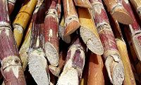
- Sugar refinery: Converts sugar cane and sugar beets into crystallized sugar and sugar syrups.
- Natural gas processing plant: Purifies and converts raw natural gas into residential, commercial and industrial fuel gas, and also recovers byproduct sulfur and natural gas liquids (NGL) such as ethane, propane, butanes and pentanes.
- Salt refinery: Converts salt (NaCl), produced by the solar evaporation of sea water, into crystallized salt used for cooking and for flavoring of food.
- Various metal refineries converting metallic ores into end product metals such as alumina, copper, gold, lead, nickel, silver, uranium, and zinc.
A typical petroleum refinery
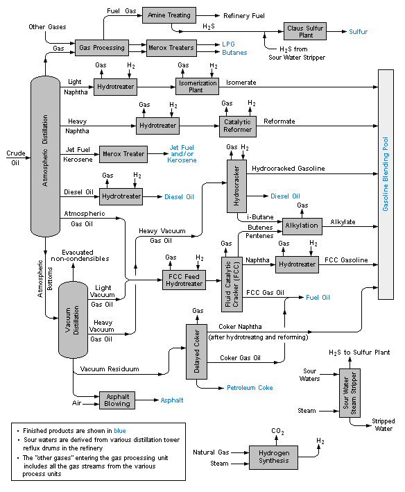
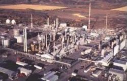
Petroleum refineries are very large industrial complexes that involve a great many different processing units and auxiliary facilities such as utility units and storage tanks. Each refinery has its own unique arrangement and combination of refining processes largely determined by the refinery location, desired products and economic considerations. There are most probably no two refineries that are identical in every respect.
The image below is a schematic flow diagram of a typical oil refinery that depicts the various unit processes and the flow of intermediate product streams that occurs between the inlet crude oil feedstock and the final end products. The diagram depicts only one of the literally hundreds of different oil refinery configurations. It does not include any of the usual refinery facilities providing utilities such as steam, cooling water, and electric power as well as storage tanks for crude oil feedstock and for intermediate products and end products.[3][4][5][6]
A typical natural gas processing plant
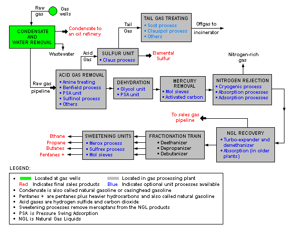
There are a great many ways in which to configure the various unit processes used in the processing of raw natural gas. The image below is a generalized, schematic block flow diagram of a typical natural gas processing plant configuration. It shows the various unit processes used to convert raw natural gas into sales gas pipelined to the end user markets.
The block flow diagram also depicts how processing of the raw natural gas yields byproduct sulfur, byproduct ethane, and natural gas liquids (NGL) such as propane, butanes and natural gasoline (denoted as pentanes +).[7][8][9][10][11]
Typical refining of sugar
Most of the sugar produced worldwide is derived either from sugar cane or sugar beets. However, the sugar produced from sugar cane is at least twice the amount produced by sugar beets. For that reason, this section deals with sugar produced from sugar cane.
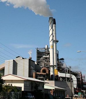
The refining of sugar cane into sugar is usually done in two stages. The first stage is the preparation and milling of freshly harvested sugar cane. In some cases, the preparation and milling may be done locally where the sugar cane is grown and harvested. In the milling stage, the sugar cane is first washed, chopped, and shredded by revolving knives. Then the shredded cane is mixed with water and crushed to produce a sugar juice.
As shown in the above schematic flow diagram,[12] the juice (containing 10 – 15 percent sucrose) is heated to about 65 – 70 °C and mixed with lime and with gaseous sulfur dioxide (SO2). The lime serves to adjust the pH of the juice to about 7.0 – 7.1 which arrests sucrose's decay into glucose and fructose, and precipitates out some impurities. The sulfur dioxide serves to decolorize the juice. The juice is then further heated to about 100 – 105 °C and sent through a clarifier where the precipitated impurities and other solids are settled out and removed.
The clarified juice is next concentrated in a multiple-effect evaporator to make a syrup with about 60 – 65 weight percent sucrose. The syrup is again treated sulfur dioxide for further decolorization and then is further concentrated under vacuum until it becomes supersaturated with sugar. Upon cooling, sugar crystallizes out of the syrup.
The crystallized sugar is separated from the residual liquid syrup (molasses)s by centrifuging. The end product is a white, crystalline sugar referred to as mill white, plantation white or crystal sugar. To produce granulated sugar, in which the individual sugar grains do not clump together, sugar must be dried. Drying is accomplished by first drying the sugar in a hot rotary dryer, and then by blowing cool air through it for several days.
The refining process described in this section is sometimes referred to as the Double Sulfation (DS) process. There are other refining processes that use calcium phosphate (instead of lime) to remove impurities from the sugar juice (and/or the sugar syrup) and treatment with activated carbon (rather than gaseous sulfur dioxide) for decolorization.
The fibrous solids, called bagasse, remaining after the crushing of the shredded sugar cane, are burned for fuel within the sugar refinery. Any surplus bagasse can be used for animal feed, in paper manufacture, or burned to generate electricity for the local power grid.
Salt refining
The equipment used in refineries
Refineries utilize a great many different types of physical equipment such as:
References
- ↑ McCabe, W., Smith, J. and Harriott, P. (2004). Unit Operations of Chemical Engineering, 7th Edition. McGraw-Hill. ISBN 0-07-284823-5.
- ↑ Perry, R.H. and Green, D.W. (Editors) (2007). Perry's Chemical Engineers' Handbook, 8th Edition. McGraw-Hill. ISBN 0-07-142294-3.
- ↑ Gary, J.H. and Handwerk, G.E. (1984). Petroleum Refining Technology and Economics, 2nd Edition. Marcel Dekker, Inc. ISBN 0-8247-7150-8.
- ↑ Guide to Refining from Chevron Oil's website
- ↑ Refinery flowchart from Universal Oil Products' website
- ↑ An example flowchart of fractions from crude oil at a refinery
- ↑ Natural Gas Processing: The Crucial Link Between Natural Gas Production and Its Transportation to Market
- ↑ Example Gas Plant
- ↑ From Purification to Liquefaction Gas Processing
- ↑ Feed-Gas Treatment Design for the Pearl GTL Project
- ↑ Benefits of integrating NGL extraction and LNG liquefaction
- ↑ Process flow diagram
See also
- Alumina
- Bagasse
- Bayer process and Hall-Héroult process (used to produce aluminium from bauxite ore)
- Liquefied Natural Gas (LNG)
- Liquefied petrolem gas (LPG)
- Natural gas
- Petroleum refinery
- Petroleum
- Sugar cane
- Sugar beet

