User:John R. Brews/WP Import: Difference between revisions
imported>John R. Brews No edit summary |
||
Line 4: | Line 4: | ||
==BJT parameters== | ==BJT parameters== | ||
The hybrid-pi model is a linearized [[two-port network]] approximation to the transistor using the small-signal base-emitter voltage <math>v_{be}</math> and collector-emitter voltage <math>v_{ce}</math> as independent variables, and the small-signal base current <math>i_{b}</math> and collector current <math>i_{c}</math> as dependent variables. (See Jaeger and Blalock.<ref name=Jaeger1/> | The hybrid-pi model is a linearized [[two-port network]] approximation to the transistor using the small-signal base-emitter voltage <math>v_{be}</math> and collector-emitter voltage <math>v_{ce}</math> as independent variables, and the small-signal base current <math>i_{b}</math> and collector current <math>i_{c}</math> as dependent variables. (See Jaeger and Blalock.<ref name=Jaeger1/>) | ||
[[Image:H pi model.png|frame|Figure 1: Simplified, low-frequency hybrid-pi [[BJT]] model.]] | [[Image:H pi model.png|frame|Figure 1: Simplified, low-frequency hybrid-pi [[BJT]] model.]] | ||
A basic, low-frequency hybrid-pi model for the [[bipolar transistor]] is shown in figure 1. The various parameters are as follows. | A basic, low-frequency hybrid-pi model for the [[bipolar transistor]] is shown in figure 1. The various parameters are as follows. |
Revision as of 12:43, 22 May 2011
The hybrid-pi model is a popular circuit model used for analyzing the small signal behavior of transistors. The model can be quite accurate for low-frequency circuits and can easily be adapted for higher frequency circuits with the addition of appropriate inter-electrode capacitances and other parasitic elements.
BJT parameters
The hybrid-pi model is a linearized two-port network approximation to the transistor using the small-signal base-emitter voltage Failed to parse (SVG (MathML can be enabled via browser plugin): Invalid response ("Math extension cannot connect to Restbase.") from server "https://wikimedia.org/api/rest_v1/":): {\displaystyle v_{be}} and collector-emitter voltage Failed to parse (SVG (MathML can be enabled via browser plugin): Invalid response ("Math extension cannot connect to Restbase.") from server "https://wikimedia.org/api/rest_v1/":): {\displaystyle v_{ce}} as independent variables, and the small-signal base current Failed to parse (SVG (MathML can be enabled via browser plugin): Invalid response ("Math extension cannot connect to Restbase.") from server "https://wikimedia.org/api/rest_v1/":): {\displaystyle i_{b}} and collector current Failed to parse (SVG (MathML can be enabled via browser plugin): Invalid response ("Math extension cannot connect to Restbase.") from server "https://wikimedia.org/api/rest_v1/":): {\displaystyle i_{c}} as dependent variables. (See Jaeger and Blalock.[1])
![](https://upload.wikimedia.org/wikipedia/commons/8/86/H_pi_model.png)
A basic, low-frequency hybrid-pi model for the bipolar transistor is shown in figure 1. The various parameters are as follows.
- Failed to parse (SVG (MathML can be enabled via browser plugin): Invalid response ("Math extension cannot connect to Restbase.") from server "https://wikimedia.org/api/rest_v1/":): {\displaystyle g_m = \frac{i_{c}}{v_{be}}\Bigg |_{v_{ce}=0} = \begin{matrix}\frac {I_\mathrm{C}}{ V_\mathrm{T} }\end{matrix} } is the transconductance in siemens, evaluated in a simple model (see Jaeger and Blalock[2])
- where:
- Failed to parse (SVG (MathML can be enabled via browser plugin): Invalid response ("Math extension cannot connect to Restbase.") from server "https://wikimedia.org/api/rest_v1/":): {\displaystyle I_\mathrm{C} \,} is the quiescent collector current (also called the collector bias or DC collector current)
- Failed to parse (SVG (MathML can be enabled via browser plugin): Invalid response ("Math extension cannot connect to Restbase.") from server "https://wikimedia.org/api/rest_v1/":): {\displaystyle V_\mathrm{T} = \begin{matrix}\frac {kT}{ q}\end{matrix}} is the thermal voltage, calculated from Boltzmann's constant, the charge on an electron, and the transistor temperature in kelvins. At 300 K (approximately room temperature) Failed to parse (SVG (MathML can be enabled via browser plugin): Invalid response ("Math extension cannot connect to Restbase.") from server "https://wikimedia.org/api/rest_v1/":): {\displaystyle V_\mathrm{T}} is about 26 mV (Google calculator).
- Failed to parse (SVG (MathML can be enabled via browser plugin): Invalid response ("Math extension cannot connect to Restbase.") from server "https://wikimedia.org/api/rest_v1/":): {\displaystyle r_{\pi} = \frac{v_{be}}{i_{b}}\Bigg |_{v_{ce}=0} = \frac{\beta_0}{g_m} = \frac{V_\mathrm{T}}{I_\mathrm{B}} \,} in ohms
- where:
- Failed to parse (SVG (MathML can be enabled via browser plugin): Invalid response ("Math extension cannot connect to Restbase.") from server "https://wikimedia.org/api/rest_v1/":): {\displaystyle \beta_0 = \frac{I_\mathrm{C}}{I_\mathrm{B}} \,} is the current gain at low frequencies (commonly called hFE). Here Failed to parse (SVG (MathML can be enabled via browser plugin): Invalid response ("Math extension cannot connect to Restbase.") from server "https://wikimedia.org/api/rest_v1/":): {\displaystyle I_B} is the Q-point base current. This is a parameter specific to each transistor, and can be found on a datasheet; Failed to parse (SVG (MathML can be enabled via browser plugin): Invalid response ("Math extension cannot connect to Restbase.") from server "https://wikimedia.org/api/rest_v1/":): {\displaystyle \beta} is a function of the choice of collector current.
- Failed to parse (SVG (MathML can be enabled via browser plugin): Invalid response ("Math extension cannot connect to Restbase.") from server "https://wikimedia.org/api/rest_v1/":): {\displaystyle r_O = \frac{v_{ce}}{i_{c}}\Bigg |_{v_{be}=0} = \begin{matrix}\frac {V_A+V_{CE}}{I_C}\end{matrix} \approx \begin{matrix} \frac {V_A}{I_C}\end{matrix}} is the output resistance due to the Early effect.
Related terms
The reciprocal of the output resistance is named the output conductance
- Failed to parse (SVG (MathML can be enabled via browser plugin): Invalid response ("Math extension cannot connect to Restbase.") from server "https://wikimedia.org/api/rest_v1/":): {\displaystyle g_{ce} = \frac {1} {r_O} } .
The reciprocal of gm is called the intrinsic resistance
- Failed to parse (SVG (MathML can be enabled via browser plugin): Invalid response ("Math extension cannot connect to Restbase.") from server "https://wikimedia.org/api/rest_v1/":): {\displaystyle r_{E} = \frac {1} {g_m} } .
MOSFET parameters
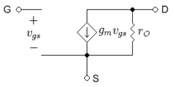
![](/wiki/images/thumb/3/3d/MOSFET_Small_Signal.png/250px-MOSFET_Small_Signal.png)
A basic, low-frequency hybrid-pi model for the MOSFET is shown in figure 2. The various parameters are as follows.
- Failed to parse (SVG (MathML can be enabled via browser plugin): Invalid response ("Math extension cannot connect to Restbase.") from server "https://wikimedia.org/api/rest_v1/":): {\displaystyle g_m = \frac{i_{d}}{v_{gs}}\Bigg |_{v_{ds}=0}}
is the transconductance in siemens, evaluated in the Shichman-Hodges model in terms of the Q-point drain current Failed to parse (SVG (MathML can be enabled via browser plugin): Invalid response ("Math extension cannot connect to Restbase.") from server "https://wikimedia.org/api/rest_v1/":): {\displaystyle I_D} by (see Jaeger and Blalock[3]):
- Failed to parse (SVG (MathML can be enabled via browser plugin): Invalid response ("Math extension cannot connect to Restbase.") from server "https://wikimedia.org/api/rest_v1/":): {\displaystyle \ g_m = \begin{matrix}\frac {2I_\mathrm{D}}{ V_{\mathrm{GS}}-V_\mathrm{th} }\end{matrix}} ,
- where:
- Failed to parse (SVG (MathML can be enabled via browser plugin): Invalid response ("Math extension cannot connect to Restbase.") from server "https://wikimedia.org/api/rest_v1/":): {\displaystyle I_\mathrm{D} } is the quiescent drain current (also called the drain bias or DC drain current)
- Failed to parse (SVG (MathML can be enabled via browser plugin): Invalid response ("Math extension cannot connect to Restbase.") from server "https://wikimedia.org/api/rest_v1/":): {\displaystyle V_{th}} = threshold voltage and Failed to parse (SVG (MathML can be enabled via browser plugin): Invalid response ("Math extension cannot connect to Restbase.") from server "https://wikimedia.org/api/rest_v1/":): {\displaystyle V_{GS}} = gate-to-source voltage.
The combination:
- Failed to parse (SVG (MathML can be enabled via browser plugin): Invalid response ("Math extension cannot connect to Restbase.") from server "https://wikimedia.org/api/rest_v1/":): {\displaystyle \ V_{ov}=( V_{GS}-V_{th})}
often is called the overdrive voltage.
- Failed to parse (SVG (MathML can be enabled via browser plugin): Invalid response ("Math extension cannot connect to Restbase.") from server "https://wikimedia.org/api/rest_v1/":): {\displaystyle r_O = \frac{v_{ds}}{i_{d}}\Bigg |_{v_{gs}=0}} is the output resistance due to channel length modulation, calculated using the Shichman-Hodges model as
- Failed to parse (SVG (MathML can be enabled via browser plugin): Invalid response ("Math extension cannot connect to Restbase.") from server "https://wikimedia.org/api/rest_v1/":): {\displaystyle r_O = \begin{matrix}\frac {1/\lambda+V_{DS}}{I_D}\end{matrix} \approx \begin{matrix} \frac {V_E L}{I_D}\end{matrix} } ,
using the approximation for the channel length modulation parameter λ[4]
- Failed to parse (SVG (MathML can be enabled via browser plugin): Invalid response ("Math extension cannot connect to Restbase.") from server "https://wikimedia.org/api/rest_v1/":): {\displaystyle \lambda =\begin{matrix} \frac {1}{V_E L} \end{matrix} } .
Here VE is a technology related parameter (about 4 V / μm for the 65 nm technology node[4]) and L is the length of the source-to-drain separation.
The reciprocal of the output resistance is named the drain conductance
- Failed to parse (SVG (MathML can be enabled via browser plugin): Invalid response ("Math extension cannot connect to Restbase.") from server "https://wikimedia.org/api/rest_v1/":): {\displaystyle g_{ds} = \frac {1} {r_O} } .
References and notes
- ↑ R.C. Jaeger and T.N. Blalock (2004). Microelectronic Circuit Design, Second Edition. New York: McGraw-Hill, Section 13.5, esp. Eqs. 13.19. ISBN 0-07-232099-0.
- ↑ R.C. Jaeger and T.N. Blalock. Eq. 5.45 pp. 242 and Eq. 13.25 p. 682. ISBN 0-07-232099-0.
- ↑ R.C. Jaeger and T.N. Blalock. Eq. 4.20 pp. 155 and Eq. 13.74 p. 702. ISBN 0-07-232099-0.
- ↑ 4.0 4.1 W. M. C. Sansen (2006). Analog Design Essentials. Dordrechtμ: Springer. ISBN 0-387-25746-2.