Relief valve
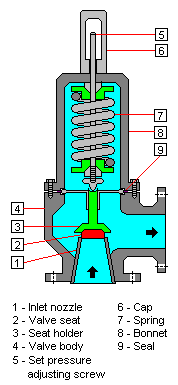
A relief valve is a type of valve used to protect pressure vessels and other equipment from being subjected to pressures that exceed their design limits.[1][2][3] Such pressure exceedances (i.e., over-pressures) can result from a system upset, an instrument or equipment failure, or a fire. The relief valve is set to open at a predetermined pressure and allow the over-pressured fluid to flow through an auxiliary route out of the system.
For safety reasons, relieving of flammable or toxic fluids should not be routed directly to the atmosphere. Thus, in most cases, the diverted fluid (liquid, gas or liquid-gas mixture) is usually routed through a piping system known as a flare header or relief header to an elevated flare stack where it is usually burned and the resulting combustion gases are released to the atmosphere.[4] As the fluid is diverted, the pressure inside the vessel will decrease. Once it decreases to the valve's re-seating pressure, the valve will re-close.
In the petroleum refining, petrochemical and chemical manufacturing, natural gas processing and power generation industries, a relief valve is also referred to as a pressure relief valve (PRV), a pressure safety valve (PSV) or simply a safety valve.
Other similar applications
In some systems, a so-called bypass valve acts as a relief valve by being used to recycle all or part of the fluid discharged by a pump or gas compressor back to either a storage vessel or to the inlet of the pump or gas compressor. This is done to protect the pump or gas compressor and any associated equipment from excessive pressure. The bypass valve and bypass path can be an integral part of the pump or compressor or externally installed as an alternate path for the pump or compressor discharge fluid. Many fire engines have such bypass systems to prevent the overpressuring the fire hoses.
In other systems, equipment must be protected against being subjected to an internal vacuum (i.e., low pressure) that is lower than the equipment can withstand. In such cases, vacuum relief valves are used to open at a predetermined low pressure limit and to admit air or an inert gas into the equipment so as control the amount of vacuum.
Legal and code requirements in industry
In most countries, industries are legally required to protect pressure vessels and other equipment by using relief valves. Also in most countries, equipment design codes such as those provided by the American Society of Mechanical Engineers(ASME), American Petroleum Institute (API) and other organizations like the British Standards Institution (BSI), the European Union (EU) and the International Organization for Standardization (ISO) must be complied with and those codes include design standards for relief valves.
The main standards, laws or directives are:
- ASME Boiler & Pressure Vessel Code, Section VIII Division 1 and Section I
- API Recommended Practice 520/521
- BSI standard EN 764-7
- EU Pressure Equipment Directive PED 97/23/EC
- ISO 4126
References
- ↑ R.W. Zappe (1998). Valve Selection Handbook, 4th Edition. Gulf Professional Publishing. ISBN 0-88415-886-1.
- ↑ Cyril F. Perry (1992). Relief Systems Handbook. Institution of Chemical Engineers. ISBN 0-85295-471-9.
- ↑ Bela G. Liptak (2003). Instrument Engineers' Handbook, 4th Edition. CRC Press. ISBN 0-8493-1083-0.
- ↑ Beychok, Milton R. (2005). Fundamentals of Stack Gas Dispersion, 4th Edition. author-published. ISBN 0964458802. See Chapter 11, Flare Stack Plume Rise.
