Operational amplifier: Difference between revisions
imported>Karl Edler (started an article) |
imported>Karl Edler (Copied in some stuff) |
||
| Line 2: | Line 2: | ||
An operational amplifier, often called an op-amp , is a DC-coupled high-gain electronic voltage amplifier with differential inputs[1] and, usually, a single output. Typically the output of the op-amp is controlled either by negative feedback, which largely determines the magnitude of its output voltage gain, or by positive feedback, which facilitates regenerative gain and oscillation. High input impedance at the input terminals and low output impedance are important typical characteristics. | |||
Op-amps are among the most widely used electronic devices today, being used in a vast array of consumer, industrial, and scientific devices. Many standard IC op-amps cost only a few cents in moderate production volume; however some integrated or hybrid operational amplifiers with special performance specifications may cost over $100 US in small quantities. | |||
[[ | Modern designs are electronically more rugged than earlier implementations and some can sustain direct short-circuits on their outputs without damage. | ||
[[ | |||
[[ | |||
== History == | |||
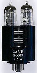
[[Image:K2-w_vaccuum_tube_op-amp.jpg|right|thumb|120px|GAP/R's K2-W: a vacuum-tube op-amp (1953)]] | |||
[[Image:Discrete_opamp.png|right|thumb|120px|GAP/R's model P45: a solid-state, discrete op-amp (1961)]] | |||
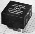
[[Image:Modular_opamp.png|right|thumb|120px|GAP/R's model PP65: a solid-state op-amp in a potted module (1962)]] | |||
[[Image:Hybrid_opamp.png|right|thumb|120px|ADI's HOS-050: a high speed hybrid IC op-amp (1979)]] | |||
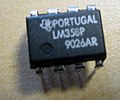
[[Image:Lm356.jpg|right|thumb|120px|An op-amp in a modern DIP package]] | |||
An op-amp, defined as a general-purpose, DC-coupled, high gain, inverting feedback [[amplifier]], is first found in US Patent 2,401,779 "Summing Amplifier" filed by Karl D. Swartzel Jr. of Bell labs in 1941. This design used three [[vacuum tube]]s to achieve a gain of 90dB and operated on voltage rails of ±350V. In contrast to modern day op-amps, it had a single inverting input and an output instead of the modern two differential inputs where one is inverting and the other is not. Throughout [[WWII]], Swartzel's design proved its value by being liberally used in the M9 [[artillery]] director designed at Bell Labs. This artillery director worked with the SCR584 [[radar]] system to achieve extraordinary hit rates (near 90%) that would not have been possible otherwise. | |||
In 1947, the op-amp was first formally defined and named in a paper by Professor John R. Ragazzoni. <!-- REFERENCE 40 in vaccuum section of JUNG --> In this same paper a footnote mentioned an op-amp design by a student that would turn out to be quite significant. This op-amp, designed by Loebe Julie, was superior in a variety of ways. It had two major innovations. Its input stage used a long-tailed [[triode]] pair with loads matched to reduce [[drift]] in the output and, far more importantly, it was the first op-amp design to have two inputs (both inverting and non-inverting). The differential input made a whole range of new functionality possible, but it would not be used for a long time due to the rise of the chopper-stabilized amplifier. | |||
In 1949, Edwin A. Goldberg, designed a [[Chopper (electronics)|chopper]] stabilized op-amp. This set-up uses a normal op-amp with an additional [[Alternating current|AC]] amplifier that goes alongside the op-amp. The chopper gets an AC signal from [[Direct current|DC]] by switching between the DC voltage and ground at a fast rate (60Hz or 400Hz). This signal is then amplified, rectified, filtered and fed into the op-amp's non-inverting input. This vastly improved the gain of the op-amp while significantly reducing the output drift and DC offset. Unfortunately, any design that used a chopper couldn't use their non-inverting input for any other purpose. Nevertheless, the much improved characteristics of the chopper-stabilized op-amp made it the dominant way to use op-amps. Techniques that used the non-inverting input regularly would not be very popular until the 1960s when op-amp [[Integrated circuit|IC]]s started to show up in the field. | |||
In 1953, vacuum tube op-amps became commercially available with the release of the K2-W from GAP/R. It sold in an octal package and had a (K2-P) chopper add-on available that would effectively "use up" the non-inverting input. This op-amp was based on a descendant of Loebe Julie's 1947 design and, along with its successors, would start the widespread use of op-amps in industry. | |||
With the birth of the [[transistor]] in 1947, and the silicon transistor in 1954, the concept of ICs became a reality. The introduction of the [[planar process]] in 1959 made transistors and ICs stable enough to be commercially useful. By 1961, solid-state, discrete op-amps were being produced. These op-amps were effectively small circuit boards with packages such as edge-connectors. They usually had hand-selected resistors in order to improve things such as voltage offset and drift. The P45 (1961) had a gain of 94dB and ran on ±15V rails. It was intended to deal with signals in the range of ±10V. By 1962, several companies were producing modular potted packages that could be plugged into [[printed circuit board]]s. These packages were crucially important as they made the operational amplifier into a single [[black box]] which could be easily treated as a component in a larger circuit. | |||
In 1963, the first monolithic IC op-amp, the μA702 designed by [[Bob Widlar]] at Fairchild Semiconductor, was released. Monolithic [[Integrated circuit|IC]]s consist of a single chip as opposed to a chip and discrete parts (a discrete IC) or multiple chips bonded and connected on a circuit board (a hybrid IC). Almost all modern op-amps are monolithic ICs; however, this first IC did not meet with much success. Issues such as an uneven supply voltage, low gain and a small dynamic range held off the dominance of monolithic op-amps until 1965 when the μA709<ref>A.P. Malvino, ''Electronic Principles'' (2nd Ed.1979. ISBN 0-07-039867-4) p.476.</ref> (also designed by Bob Widlar) was released. The popularity of monolithic op-amps was further improved upon the release of the LM101 in 1967, which solved a variety of issues and the subsequent release of the μA741 in 1968. The μA741 was extremely similar to the LM101 except that Fairchild's facilities allowed them to include a 30pF compensation capacitor inside the chip instead of requiring external compensation. This simple difference has made the 741 ''the'' canonical op-amp and many modern amps base their pinout on the 741's.The μA741 is still in production, and has become ubiquitous in electronics — many manufacturers produce a version of this classic chip, recognizable by part numbers containing "741." | |||
Since the 741, there have been many different directions taken in op-amp design. [[Varactor]] bridge op-amps started to be produced in the late 1960s; they were designed to have extremely small input current are still amongst the best op-amps available in terms of common-mode rejection with the ability to correctly deal with 100s of Volts at its inputs. In the 1970s high speed, low-input current designs started to be made by using [[Field-effect transistor|FET]]s. These would be largely replaced by op-amps made with [[MOSFET]]s in the 1980s. During the 1970s single sided supply op-amps also became available. The LM324 (released in 1972) was one such op-amp that came in a quad package and became an industry standard. In addition to packaging multiple op-amps in a single package, the 1970s also saw the birth of op-amps in hybrid packages. These op-amps were generally improved versions of existing monolithic op-amps and were without a doubt the best op-amps available. As the properties of monolithic op-amps improved, the more complex hybrid ICs were quickly relegated to systems that are required to have extremely long service lives or other specialty systems. | |||
=== Timeline === | |||
1941: First (vacuum tube) op-amp<br /> | |||
1947: First op-amp with an explicit non-inverting input<br /> | |||
1948: First chopper-stabilized op-amp9<br /> | |||
1961: First discrete IC op-amps<br /> | |||
1962: First op-amps in potted modules<br /> | |||
1963: First monolithic IC op-amp<br /> | |||
1966: First varactor bridge op-amps<br /> | |||
1968: Release of the μA741 - would be seen as a nearly ubiquitous chip<br /> | |||
1970: First high-speed, low-input current FET design<br /> | |||
1972: Single sided supply op-amps being produced | |||
Revision as of 15:55, 9 June 2008
An operational amplifier, commonly known as an op-amp, is a device used to amplify the difference between two electrical signals. They are a building block for many analog circuits.
An operational amplifier, often called an op-amp , is a DC-coupled high-gain electronic voltage amplifier with differential inputs[1] and, usually, a single output. Typically the output of the op-amp is controlled either by negative feedback, which largely determines the magnitude of its output voltage gain, or by positive feedback, which facilitates regenerative gain and oscillation. High input impedance at the input terminals and low output impedance are important typical characteristics.
Op-amps are among the most widely used electronic devices today, being used in a vast array of consumer, industrial, and scientific devices. Many standard IC op-amps cost only a few cents in moderate production volume; however some integrated or hybrid operational amplifiers with special performance specifications may cost over $100 US in small quantities.
Modern designs are electronically more rugged than earlier implementations and some can sustain direct short-circuits on their outputs without damage.
History
An op-amp, defined as a general-purpose, DC-coupled, high gain, inverting feedback amplifier, is first found in US Patent 2,401,779 "Summing Amplifier" filed by Karl D. Swartzel Jr. of Bell labs in 1941. This design used three vacuum tubes to achieve a gain of 90dB and operated on voltage rails of ±350V. In contrast to modern day op-amps, it had a single inverting input and an output instead of the modern two differential inputs where one is inverting and the other is not. Throughout WWII, Swartzel's design proved its value by being liberally used in the M9 artillery director designed at Bell Labs. This artillery director worked with the SCR584 radar system to achieve extraordinary hit rates (near 90%) that would not have been possible otherwise.
In 1947, the op-amp was first formally defined and named in a paper by Professor John R. Ragazzoni. In this same paper a footnote mentioned an op-amp design by a student that would turn out to be quite significant. This op-amp, designed by Loebe Julie, was superior in a variety of ways. It had two major innovations. Its input stage used a long-tailed triode pair with loads matched to reduce drift in the output and, far more importantly, it was the first op-amp design to have two inputs (both inverting and non-inverting). The differential input made a whole range of new functionality possible, but it would not be used for a long time due to the rise of the chopper-stabilized amplifier.
In 1949, Edwin A. Goldberg, designed a chopper stabilized op-amp. This set-up uses a normal op-amp with an additional AC amplifier that goes alongside the op-amp. The chopper gets an AC signal from DC by switching between the DC voltage and ground at a fast rate (60Hz or 400Hz). This signal is then amplified, rectified, filtered and fed into the op-amp's non-inverting input. This vastly improved the gain of the op-amp while significantly reducing the output drift and DC offset. Unfortunately, any design that used a chopper couldn't use their non-inverting input for any other purpose. Nevertheless, the much improved characteristics of the chopper-stabilized op-amp made it the dominant way to use op-amps. Techniques that used the non-inverting input regularly would not be very popular until the 1960s when op-amp ICs started to show up in the field.
In 1953, vacuum tube op-amps became commercially available with the release of the K2-W from GAP/R. It sold in an octal package and had a (K2-P) chopper add-on available that would effectively "use up" the non-inverting input. This op-amp was based on a descendant of Loebe Julie's 1947 design and, along with its successors, would start the widespread use of op-amps in industry.
With the birth of the transistor in 1947, and the silicon transistor in 1954, the concept of ICs became a reality. The introduction of the planar process in 1959 made transistors and ICs stable enough to be commercially useful. By 1961, solid-state, discrete op-amps were being produced. These op-amps were effectively small circuit boards with packages such as edge-connectors. They usually had hand-selected resistors in order to improve things such as voltage offset and drift. The P45 (1961) had a gain of 94dB and ran on ±15V rails. It was intended to deal with signals in the range of ±10V. By 1962, several companies were producing modular potted packages that could be plugged into printed circuit boards. These packages were crucially important as they made the operational amplifier into a single black box which could be easily treated as a component in a larger circuit.
In 1963, the first monolithic IC op-amp, the μA702 designed by Bob Widlar at Fairchild Semiconductor, was released. Monolithic ICs consist of a single chip as opposed to a chip and discrete parts (a discrete IC) or multiple chips bonded and connected on a circuit board (a hybrid IC). Almost all modern op-amps are monolithic ICs; however, this first IC did not meet with much success. Issues such as an uneven supply voltage, low gain and a small dynamic range held off the dominance of monolithic op-amps until 1965 when the μA709[1] (also designed by Bob Widlar) was released. The popularity of monolithic op-amps was further improved upon the release of the LM101 in 1967, which solved a variety of issues and the subsequent release of the μA741 in 1968. The μA741 was extremely similar to the LM101 except that Fairchild's facilities allowed them to include a 30pF compensation capacitor inside the chip instead of requiring external compensation. This simple difference has made the 741 the canonical op-amp and many modern amps base their pinout on the 741's.The μA741 is still in production, and has become ubiquitous in electronics — many manufacturers produce a version of this classic chip, recognizable by part numbers containing "741."
Since the 741, there have been many different directions taken in op-amp design. Varactor bridge op-amps started to be produced in the late 1960s; they were designed to have extremely small input current are still amongst the best op-amps available in terms of common-mode rejection with the ability to correctly deal with 100s of Volts at its inputs. In the 1970s high speed, low-input current designs started to be made by using FETs. These would be largely replaced by op-amps made with MOSFETs in the 1980s. During the 1970s single sided supply op-amps also became available. The LM324 (released in 1972) was one such op-amp that came in a quad package and became an industry standard. In addition to packaging multiple op-amps in a single package, the 1970s also saw the birth of op-amps in hybrid packages. These op-amps were generally improved versions of existing monolithic op-amps and were without a doubt the best op-amps available. As the properties of monolithic op-amps improved, the more complex hybrid ICs were quickly relegated to systems that are required to have extremely long service lives or other specialty systems.
Timeline
1941: First (vacuum tube) op-amp
1947: First op-amp with an explicit non-inverting input
1948: First chopper-stabilized op-amp9
1961: First discrete IC op-amps
1962: First op-amps in potted modules
1963: First monolithic IC op-amp
1966: First varactor bridge op-amps
1968: Release of the μA741 - would be seen as a nearly ubiquitous chip
1970: First high-speed, low-input current FET design
1972: Single sided supply op-amps being produced
- ↑ A.P. Malvino, Electronic Principles (2nd Ed.1979. ISBN 0-07-039867-4) p.476.


