Negative feedback amplifier
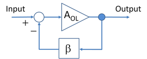
A negative feedback amplifier (or more commonly simply a feedback amplifier) is an amplifier in which a fraction of its output is combined with the signal at its input that opposes the signal in what is called negative feedback. The negative feedback improves performance (linearity, frequency response, step response) and reduces sensitivity to parameter variations due to manufacturing or environmental uncertainties. A single feedback loop with unilateral blocks (blocks that transmit signals only in one direction) is shown in the figure. Negative feedback is used in this way in many amplifiers and control systems.[1]
Advantages and disadvantages of feedback
Many electronic devices used to provide gain (for example, vacuum tubes, Bipolar transistors, MOSFETs) are nonlinear. Negative feedback is a circuit technique that trades gain for higher linearity (reducing distortion), amongst other things. If not designed correctly amplifiers with negative feedback can become unstable, resulting in unwanted behavior, such as oscillation. The Nyquist stability criterion developed by Harry Nyquist of Bell Laboratories, or the Bode plot can be used to study the stability of feedback amplifiers.
Feedback amplifiers share these properties:[2]
Advantages:
- Can increase or decrease input impedance (depending on type of feedback)
- Can increase or decrease output impedance (depending on type of feedback)
- Reduces distortion (increases linearity)
- Increases bandwidth (the range of frequencies for which the circuit works)
- Desensitizes gain to component variations
- Can control step response of amplifier
Liabilities:
- May lead to instability if not designed carefully
- The gain of the amplifier decreases
- The input and output impedances of the amplifier with feedback (the closed-loop amplifier) become sensitive to the gain of the amplifier without feedback (the open-loop amplifier); that exposes these impedances to variations in the open loop gain, for example, due to parameter variations or due to nonlinearity of the open-loop gain
History
The negative feedback amplifier was invented by Harold Stephen Black (US patent 2,102,671, filed 1932, issued 1937[3]) while a passenger on the Lackawanna Ferry (from Hoboken Terminal to Manhattan) on his way to work at Bell Laboratories on August 2, 1927. Black had been pondering how to reduce distortion in repeater amplifiers used for telephone transmission. On a blank space in his copy of The New York Times, currently on display at Bell Laboratories in Mountainside, New Jersey, he sketched a diagram equivalent to that in the figure, and derived the equations below.[4]
Classical feedback
Voltage amplifiers
Below, the gain of the amplifier with feedback, the closed-loop gain Afb, is derived in terms of the gain of the amplifier without feedback, the open-loop gain AOL and the feedback factor β, which governs how much of the output signal is applied to the input. See the figure, top right. The feedback parameter β is determined by the feedback network that is connected around the amplifier.
Consider a voltage amplifier with voltage feedback. Without feedback, the output voltage Vout = AOL Vin, where the open-loop gain AOL in general may be a function of both frequency and voltage.
The open-loop gain AOL is defined by:
where Vin is the input to the amplifier, with no feedback, and Vout is the amplifier output, again with no feedback.
Suppose we have a feedback loop so that a fraction β Vout of the output is subtracted from the input. The input to the amplifier itself is now V’in, where
The gain of the amplifier with feedback, called the closed-loop gain, Afb still is given by,
but now the signal increased by the gain of the amplifier is V’in. That is,
Rewriting the expression for V’in:
or:
Solving for Afb:
If AOL >> 1, then Afb ≈ 1 / β and the effective amplification (or closed-loop gain) Afb is set by the feedback constant β, and hence set by the feedback network, usually a simple reproducible network, thus making linearizing and stabilizing the amplification characteristics straightforward. Note also that if there are conditions where β AOL = −1, the amplifier has infinite amplification – it has become an oscillator, and the system is unstable. The stability characteristics of the gain feedback product β AOL are often displayed and investigated on a Nyquist plot (a polar plot of the gain/phase shift as a parametric function of frequency). A simpler, but less general technique, uses Bode plots.
The combination L = β AOL appears commonly in feedback analysis and is called the loop gain. The combination ( 1 + β AOL ) also appears commonly and is variously named as the desensitivity factor or the improvement factor.
Bandwidth extension
- See also: Pole splitting and Bode plot
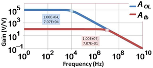
Feedback can be used to extend the bandwidth of an amplifier (speed it up) at the cost of lowering the amplifier gain.[5] The figure at right shows such a comparison. The figure is understood as follows. Without feedback the so-called open-loop gain in this example has a single time constant frequency response given by
where A0 is the zero-frequency gain of the amplifier, and fC is the cutoff or corner frequency of the amplifier. In this example, the gain at zero frequency is A0 = 105 V/V and the corner frequency is fC = 104 Hz. The figure shows the gain is flat out to the corner frequency and then drops. When feedback is present the so-called closed-loop gain, as shown in the formula of the previous section, becomes,
The last expression shows the feedback amplifier still has a single time constant behavior, but the corner frequency is now increased from the value fC by the improvement factor (1+β A0) to become (1+β A0) fC, and the gain at zero frequency has dropped by exactly the same factor. This reciprocal behavior is called the gain-bandwidth tradeoff. In Figure 2, (1 + β A0) = 103, so Afb(0)= 105 / 103 = 100 V/V, and fC increases to 104 × 103 = 107 Hz.
Multiple poles
When the open-loop gain has several poles, rather than the single pole of the above example, feedback can result in complex poles (real and imaginary parts). In a two-pole case, the result is peaking in the frequency response of the feedback amplifier near its corner frequency, and ringing and overshoot in its its step response. In the case of more than two poles, the feedback amplifier can become unstable, and oscillate. See the discussion of gain margin and phase margin.[6]
Asymptotic gain model
In the above analysis the feedback network is unilateral. However, real feedback networks often exhibit feed forward as well, that is, they feed a small portion of the input to the output, degrading performance of the feedback amplifier. A more general way to model negative feedback amplifiers including this effect is with the asymptotic gain model.
Feedback and amplifier type
- See also: Two-port network
Amplifiers use current or voltage as input and output, so four types of amplifier are possible, choosing one of the two inputs and pairing with one of the two outputs. Any of these four choices may be the open-loop amplifier used to construct the feedback amplifier. The objective for the feedback amplifier also may be any one of the four types of amplifier, not necessarily the the same type as the open-loop amplifier. For example, an op amp (voltage amplifier) can be arranged to make a current amplifier instead. The conversion from one type to another is implemented using different feedback connections, usually referred to as series or shunt (parallel) connections.[7][8] See the table below.
| Feedback amplifier type | Input connection | Output connection | Ideal feedback | Two-port feedback |
|---|---|---|---|---|
| Current | Shunt | Series | CCCS | g-parameter |
| Transresistance | Shunt | Shunt | VCCS | y-parameter |
| Transconductance | Series | Series | CCVS | z-parameter |
| Voltage | Series | Shunt | VCVS | h-parameter |
The feedback can be implemented using a two-port network. There are four types of two-port network, and the selection depends upon the type of feedback. In the table, the notation VCVS = voltage-controlled voltage source, CCCS=current-controlled current source and so forth.
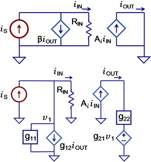
The example of a current feedback amplifier is shown in the figure. In the ideal feedback amplifier (top), current at the output controls the ideal current source in the input. The feedback is performed ideally using a current-controlled current source (CCCS) to subtract βiOUT from the signal current. The terminology is that the output current is sampled by the input, and combined with current at the input. In practice, the feedback can be provided by an imperfect feedback circuit (bottom). Supposing the feedback can be approximated as a two-port network, to obtain current feedback this two-port must incorporate a CCCS, that is, the appropriate choice for feedback network is a g-parameter two-port. Then the required feedback is provided by the dependent current source as g12iOUT. As shown in the figure, however, any such feedback implementation is likely to suffer from several non-ideal characteristics: (i) it loads the output unless g22 is a short-circuit, (ii) it provides feedforward through g21 unless v1 is zero, (iii) it loads the input through g11 unless this is an open-circuit.
References and notes
- ↑ Kuo, Benjamin C & Farid Golnaraghi (2003). Automatic control systems, Eighth edition. NY: Wiley. ISBN 0471134767.
- ↑ Gaetano Palumbo and Salvatore Pennisi (2002). “Chapter 3: Feedback”, Feedback amplifiers: theory and design. Springer, p. 64. ISBN 0792376439.
- ↑ Wave translation system. Retrieved on 2011-06-24. Patent 2,106,671 refers to "apparatus or systems involving negative feedback".
- ↑ Fred F. Waldhauer (1982). Feedback. NY: Wiley, p. 3, Figure 1.1 p. 4, p. 8. ISBN 0471053198.
- ↑ RW Brodersen. Analog circuit design: lectures on stability. Retrieved on 2011-06-24.
- ↑ For a complete discussion, see Willy M. C. Sansen (2006). Analog design essentials. New York; Berlin: Springer, §0513-§0533, p. 155-165. ISBN 0-387-25746-2.
- ↑ Ashok K. Goel. Feedback topologies. Retrieved on 2011-06-24.
- ↑ Zimmer T & Geoffreoy D. Feedback amplifier. Retrieved on 2011-06-24.


