Petroleum refining processes
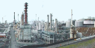
Petroleum refining processes are those chemical engineering processes and other facilities used in petroleum refineries (also referred to as oil refineries) to transform crude oil into useful products such as liquefied petroleum gas (LPG), gasoline or petrol, kerosene, jet fuel, diesel oil and fuel oils.[1][2]
Petroleum refineries are very large industrial complexes that involve a great many different processing units and auxiliary facilities such as utility units and storage tanks. Each refinery has its own unique arrangement and combination of refining processes largely determined by the refinery location, desired products and economic considerations. There are most probably no two refineries that are identical in every respect.
Processing units used in refineries
- Crude Oil Distillation unit: Distills the incoming crude oil into various fractions for further processing in other units.
- Vacuum Distillation unit: Further distills the residue oil from the bottom of the crude oil distillation unit. The vacuum distillation is performed at a pressure well below atmospheric pressure.
- Naphtha Hydrotreater unit: Uses hydrogen to desulfurize the naphtha fraction from the crude oil distillation or other units within the refinery.
- Catalytic Reformer unit: Converts the desulfurized naphtha molecules into higher-octane molecules to produce reformate, which is a component of the end-product gasoline or petrol.
- Alkylation unit: Converts isobutane and butylenes into alkylate, which is a very high-octane component of the end-product gasoline or petrol.
- Isomerization unit: Converts linear molecules such as normal pentane into higher-octane branched molecules for blending into the end-product gasoline. Also used to convert linear normal butane into isobutane for use in the alkylation unit.
- Distillate Hydrotreater unit: desulfurizes some of the other distilled fractions from the crude oil distillation unit (such as diesel oil).
- Merox or similar units: Desulfurize LPG, kerosene or jet fuel by oxidizing undesired mercaptans to organic disulfides.
- Amine gas treater, Claus unit, and tail gas treatment for converting hydrogen sulfide gas from the hydrotreaters into end-product elemental sulfur.
- Fluid Catalytic Cracking (FCC) unit: Upgrades the heavier, higher-boiling fractions from the the crude oil distillation by converting them into lighter and lower boiling, more valuable products.
- Hydrocracker unit: Uses hydrogen to upgrade heavier fractions from the crude oil distillation and the vacuum distillation units into lighter, more valuable products.
- Visbreaker unit upgrades heavy residual oils from the vacuum distillation unit by thermally cracking them into lighter, more valuable reduced viscosity products.
- Delayed coking and Fluid coker units: Convert very heavy residual oils into end-product petroleum coke as well as naphtha and diesel oil by-products.
Auxiliary facilities required in refineries
- Steam reforming unit: Converts natural gas into hydrogen for the hydrotreaters and/or the hydrocracker.
- Sour water stripper unit: Uses steam to remove hydrogen sulfide gas from various wastewater streams for subsequent conversion into end-product sulfur in the Claus unit.[3]
- Utility units such as cooling towers for furnishing circulating cooling water, boiler plants for generating steam, instrument air systems for pneumatically operated control valves and an electrical substation.
- Wastewater collection and treating systems consisting of API separators, dissolved air flotation (DAF) units and some type of further treatment (such as an activated sludge biotreater) to make the wastewaters suitable for reuse or for disposal.[3]
- Liquified gas (LPG) storage vessels for propane and similar gaseous fuels at a pressure sufficient to maintain them in liquid form. These are usually spherical vessels or bullets (horizontal vessels with rounded ends).
- Storage tanks for crude oil and finished products, usually vertical, cylindrical vessels with some sort of vapor emission control and surrounded by an earthen berm to contain liquid spills.
The crude oil distillation unit
The crude oil distillation unit (CDU) is the first processing unit in virtually all petroleum refineries. The CDU distills the incoming crude oil into various fractions of different boiling ranges, each of which are then processed further in the other refinery processing units. The CDU is often referred to as the atmospheric distillation unit because it operates at slightly above atmospheric pressure.
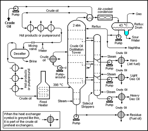
Below is a schematic flow diagram of a typical crude oil distillation unit. The incoming crude oil is preheated by exchanging heat with some of the hot, distilled fractions and other streams. It is then desalted to remove inorganic salts (primarily sodium chloride).
Following the desalter, the crude oil is further heated by exchanging heat with some of the hot, distilled fractions and other streams. It is then heated in a fuel-fired furnace (fired heater) to a temperature of about 398 °C and routed into the bottom of the distillation unit.
The cooling and condensing of the distillation tower overhead is provided partially by exchanging heat with the incoming crude oil and partially by either an air-cooled or water-cooled condenser. Additional heat is removed from the distillation column by a pumparound system as shown in the diagram below.
The fractions removed from the side of the distillation column at various points between the column top and bottom are called sidecuts. Each of the sidecuts (i.e., the kerosene, light gas oil and heavy gas oil) is cooled by exchanging heat with the incoming crude oil. All of the fractions (i.e., the overhead naphtha, the sidecuts and the bottom residue) are sent to intermediate storage tanks before being processed further.
Flow diagram of a typical petroleum refinery
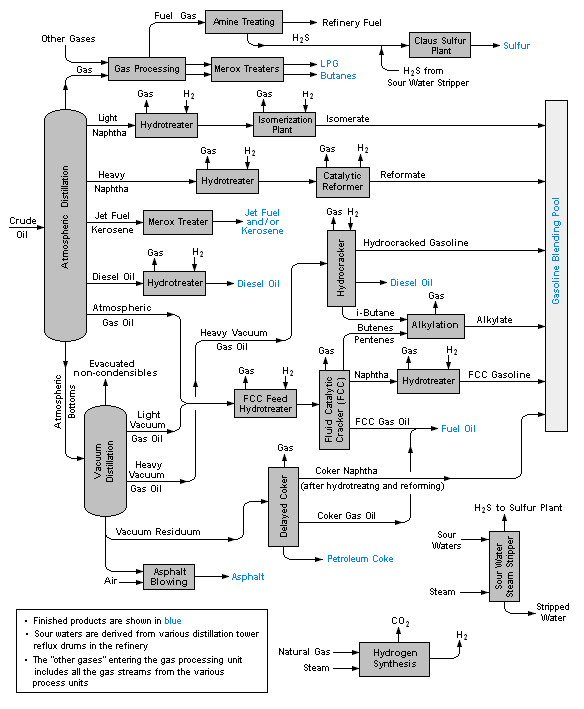
The image below is a schematic flow diagram of a typical petroleum refinery that depicts the various refining processes and the flow of intermediate product streams that occurs between the inlet crude oil feedstock and the final end-products.
The diagram depicts only one of the literally hundreds of different oil refinery configurations. The diagram also does not include any of the usual refinery facilities providing utilities such as steam, cooling water, and electric power as well as storage tanks for crude oil feedstock and for intermediate products and end products.[1][2][4][5]
See also
References
- ↑ 1.0 1.1 Gary, J.H. and Handwerk, G.E. (1984). Petroleum Refining Technology and Economics, 2nd Edition. Marcel Dekker, Inc. ISBN 0-8247-7150-8.
- ↑ 2.0 2.1 Leffler, W.L. (1985). Petroleum refining for the nontechnical person, 2nd Edition. PennWell Books. ISBN 0-87814-280-0.
- ↑ 3.0 3.1 Beychok, Milton R. (1967). Aqueous Wastes from Petroleum and Petrochemical Plants, 1st Edition. John Wiley & Sons. Library of Congress Control Number 67019834.
- ↑ Guide to Refining from Chevron Oil's website
- ↑ Refinery flowchart from the website of Universal Oil Products
- Pages using ISBN magic links
- Editable Main Articles with Citable Versions
- CZ Live
- Engineering Workgroup
- Chemistry Workgroup
- Chemical Engineering Subgroup
- Articles written in American English
- Advanced Articles written in American English
- All Content
- Engineering Content
- Chemistry Content
- Chemical Engineering tag


