CZ:Cold Storage/GF Engineering Material: Difference between revisions
imported>Gordan Feric No edit summary |
imported>Chris Day No edit summary |
||
| Line 1: | Line 1: | ||
{{subpages}} | |||
This article addresses analysis of '''energy conversion''' as it pertains to power cycles (Carnot, Brayton, Otto and Diesel), power cycle components/processes (compression, combustion and expansion) and compressible flow (nozzle, diffuser and thrust) ideal operation, T - s diagrams and performance trends. | This article addresses analysis of '''energy conversion''' as it pertains to power cycles (Carnot, Brayton, Otto and Diesel), power cycle components/processes (compression, combustion and expansion) and compressible flow (nozzle, diffuser and thrust) ideal operation, T - s diagrams and performance trends. | ||
{{TOC-right}} | {{TOC-right}} | ||
Revision as of 01:04, 2 February 2009
The {{subpages}} template is designed to be used within article clusters and their related pages.
It will not function on CZ pages.
This article addresses analysis of energy conversion as it pertains to power cycles (Carnot, Brayton, Otto and Diesel), power cycle components/processes (compression, combustion and expansion) and compressible flow (nozzle, diffuser and thrust) ideal operation, T - s diagrams and performance trends. Template:TOC-right
Power cycle analysis
In this section dealing power cycles, ideal and isentropic operation of Carnot, Brayton, Otto and Diesel cycles and their preformance trends are presented.
Carnot cycle
In the presented Carnot Cycle analysis, only air is considered as the working fluid behaving as a perfect gas -- specific heat has a constant value. Ideal gas state equation is valid -- pv = RT.
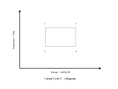
Figure 1 contains a Carnot Cycle schematic layout. Air enters a compressor at point 1, and exits the compressor at point 2. Isentropic compression is considered with no entropy change. Air enters a heat exchanger -- heat addition -- at point 2, and exits the heat exchanger at point 3. At a constant temperature, heat addition takes place. Air enters a turbine at point 3, and exits the turbine at point 4. Isentropic expansion is considered with no entropy change. Air enters a heat exchanger -- heat rejection -- at point 4, and exits the heat exchanger at point 1. At a constant temperature, heat rejection takes place. It should be mentioned that air at point 1 enters the compressor and the cycle is repeated.
Figure 2 presents a Carnot Cycle entropy vs temperature diagram.
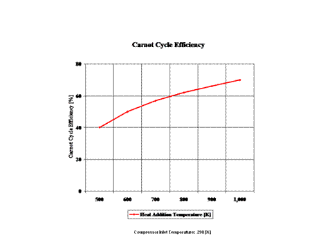
Figure 3 presents the Carnot Cycle efficiency as a function of the heat addition temperature. It should be noted that the compressor inlet tempearture is at standard ambient conditions of 298 [K] and 1 [atm] of absolute pressure.
Figure 4 presents the Carnot Cycle efficiency as a function of the heat rejection temperature. It should be noted that the turbine inlet temperature is at 800 [K].
The Carnot Cycle efficiency increases with an increase in the heat addition temperature when the heat rejection temperature does not change at all. Furthermore, the Carnot Cycle efficiency decreases with an increase in the heat rejection temperature when the heat addition temperature does not change at all.
The Carnot Cycle efficiency is not dependant on the working fluid properties.
The governing equations are as follows:
T2/T1 = (p2/p1)(k-1)/k
T3/T4 = (p3/p4)k-1)/k
ϰ = cp/cv
pv = RT
η = 1 - T1/T2
Input data are as follows:
T1 = 298 [K]
p1 = 1 [atm]
cp = 1.004 [kJ/kg*K]
ϰ = cp/cv - for air ϰ = 1.4 [/]
Brayton cycle
In the presented Brayton cycle analysis, only air is considered as the working fluid behaving as a perfect gas -- specific heat has a constant value. Ideal gas state equation is valid -- pv = RT.
A gas turbine is a heat engine that uses a high temperature, high pressure gas as the working fluid. Combustion of a fuel in air is usually used to produce the needed temperatures and pressures in the gas turbine, which is why gas turbines are often referred to as combustion turbines. Expansion of the high temperature, high pressure working fluid takes place in the gas turbine. The gas turbine shaft rotation drives an electric generator and a compressor for the working fluid, air, used in the gas turbine combustor. Many gas turbines also use a heat exchanger called a recouperator to impart turbine exhaust heat into the combustor's air/fuel mixture. Gas turbines produce high quality heat that can be used to generate steam for combined heat and power and combined-cycle applications, significantly enhancing efficiency.
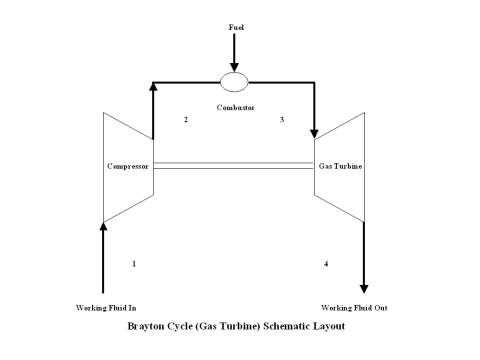
The initial state of the working fluid, air, is assumed to be at point 1 at the atmospheric conditions, 298 [K] temperature and 1 [atm] pressure. The working fluid is compressed, isentropically, along line 1-2 by a compressor and enters the combustor. At a constant pressure, combustion takes place, fuel is added to the combustor and the working fluid temperature raises. High temperature working fluid exits the combustor at point 3. Then the working fluid enters a gas turbine where an isentropic expansion occurs, producing power. The working fluid exits the gas turbine at point 4. It should be mentioned that the working fluid at point 1 enters the compressor and the cycle is repeated.
A schematic layout of the ideal, open Brayton cycle is shown in Figure 1.
The changes in the state of the working fluid, air, are presented in a T - s diagram in Figure 2.
It should be pointed out that this material deals with the open Brayton cycle. The way how the T - s diagram is presented, it describes a closed Brayton cycle -- this would require a heat exchanger after point 4 where the working fluid would be cooled down to point 1 and the cycle repeats. Therefore, the T - s diagram is presented as a closed Brayton cycle to allow easier understanding and derivation of the Brayton cycle thermal efficiency -- heat addition and heat rejection.
The gas turbine and compressor are connected by shaft so the considerable amount of work done on the gas turbine is used to power the compressor.
It can be noticed from the T - s diagram that the work done on the gas turbine is greater than the work necessary to power the compressor -- constant pressure lines in the T - s diagram diverge by going to the right side (entropy wise).
The thermal cycle efficiency can be given as a function of specific external work (specific net power output) and added heat to the working fluid as follows:
η = w/qh = (wt - wc)/qh = (qh - ql)/qh
or
η = 1 - ql/qh = 1 - (cp(T4 - T1))/(cp(T3 - T2)) = 1 - (T1(T4/T1 - 1))/(T2(T3/T2 - 1))
where
η - thermal efficiency [/]
w - specific external work (specific net power output) [kJ/kg]
wt - expansion specific power output [kJ/kg]
wc - compression specific power input [kJ/kg]
Wt - expansion power output [kW]
Wc - compression power input [kW]
qh - added heat to the working fluid [kJ/kg]
ql - heat rejected from the working fluid [kJ/kg]
cp - specific heat at constant pressure [kJ/kg*K]
cv - specific heat at constant volume [kJ/kg*K]
m - working fluid mass flow rate [kg/s]
For isentropic turbine and compressor
p3/p4 = (T3/T4)ϰ/(ϰ-1)
p2/p1 = (T2/T1)ϰ/(ϰ-1)
Knowing that
p3/p4 = p2/p1
where
ϰ = cp/cv - for air ϰ = 1.4 [/]
p1, p2, p3, p4 - pressure values at points 1, 2, 3 and 4 [atm]
T1, T2, T3, T4 - temperature values at points 1, 2, 3 and 4 [K]
It follows that
T3/T4 = T2/T1
or
T3/T2 = T4/T1
Therefore, after some mathematical operations the thermal efficiency is:
η = 1 - T1/T2 = 1 - T4/T3
If the temperature ratio is substituted in terms of the pressure ratio:
η = 1 - 1/rp(ϰ-1)/ϰ
where
rp - pressure ratio p2/p1 [/]
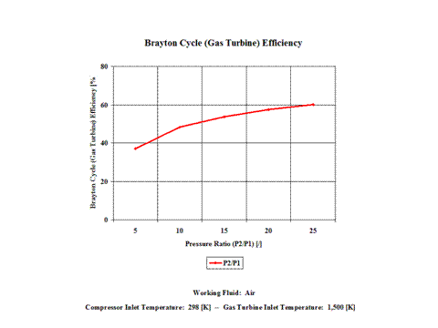
The derived Brayton cycle thermal efficiency depends on the pressure ratio and on the working fluid. In Figure 3, it is shown the thermal efficiency increases with the pressure ratio. In this material, air is the only working fluid analyzed. However, it can be concluded that the thermal efficiency increases with the higher value for ϰ, which is a ratio of gas specific heat values (cp/cv).
Here, two general performance trends are considered. First, impact of the gas turbine inlet temperature and compressor pressure ratio on the Brayton cycle specific power output and second, impact of the working mass flow rate on the Brayton cycle power output.
Figure 4 presents the results of the first performance trend, while Figure 5 presents the results of the second trend.
One can notice that the Brayton cycle specific power output increases with an increase in the gas turbine inlet temperature. Furthermore, the increase is greater for the higher compressor pressure ratio.
One can notice that the Brayton cycle power output increases with an increase in the working fluid mass flow rate. The increase is greater for the higher compressor pressure ratio.
The general assumptions are as follows:
Compression and expansion processes are reversible and adiabatic – isentropic. The working fluid has the same composition throughout the cycle. Ideal gas state equation is valid -- pv = RT. Air behaves as a perfect gas -- specific heat has a constant value.
The governing equations are as follows:
p3/p4 = (T3/T4)ϰ/(ϰ-1)
p2/p1 = (T2/T1)ϰ/(ϰ-1)
ϰ = cp/cv
pv = RT
wc = cp(T2 - T1)
Wc = cp(T2 - T1)m
wt = cp(T3 - T4)
Wt = cp(T3 - T4)m
η = 1 - 1/rp(ϰ-1)/ϰ
rp = p2/p1
Input data are as follows:
T1 = 298 [K]
p1 = 1 [atm]
T3 = 900, 1,200 and 1,500 [K]
p3 = 5 and 15 [atm]
cp = 1.004 [kJ/kg*K]
ϰ = cp/cv - for air ϰ = 1.4 [/]
m = 50, 100 and 150 [kg/s]
The results are as follows:
| Pressure Ratio
[/] |
Efficiency
[%] |
|---|---|
| Specific Power Output
[kW/kg/s] |
Gas Turbine Inlet Temperature
[K] | ||
|---|---|---|---|
| Pressure Ratio
[/] |
900 | 1,200 | 1,500 |
| Power Output
[MW] |
Mass Flow Rate
[kg/s] | ||
|---|---|---|---|
| Pressure Ratio
[/] |
50 | 100 | 150 |
The Brayton cycle thermal efficiency depends on the pressure ratio and on the working fluid. The thermal efficiency increases with the pressure ratio. Also, the thermal efficiency increases with the higher value for ϰ, which is a ratio of gas specific heat values (cp/cv).
The Brayton cycle specific power output increases with an increase in the gas turbine inlet temperature. Furthermore, the increase is greater for the higher compressor pressure ratio.
The Brayton cycle power output increases with an increase in the working fluid mass flow rate. The increase is greater for the higher compressor pressure ratio.
Otto cycle
In the presented Otto cycle analysis, only air is considered as the working fluid behaving as the perfect gas -- specific heat has a constant value. Ideal gas state equation is valid -- pv = RT.
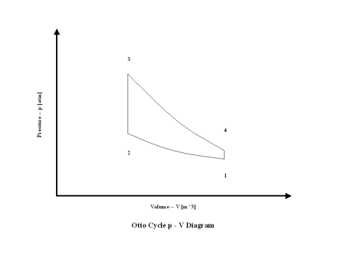
Figure 1 contains an Otto cycle pressure vs volume diagram. Air enters a cylinder at point 1 when compression starts, and compression ends at point 2. Isentropic compression is considered with no entropy change. Heat addition starts at point 2, and heat addition ends at point 3. At a constant volume, air gets heated and the working fluid temperature raises. Expansion starts at point 3, and expansion ends at point 4. Isentropic expansion is considered with no entropy change. Air heat rejection starts at point 4, and heat rejection ends at point 1. At a constant volume, air gets cooled and the working fluid temperature goes down. It should be mentioned that air at point 1 enters the compression process again and the cycle is repeated.
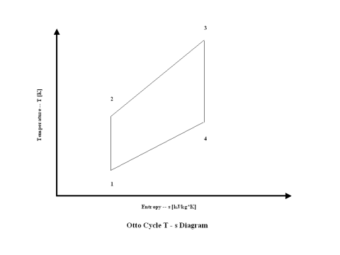
Figure 2 presents an Otto Cycle entropy vs temperature diagram.
The thermal cycle efficiency can be given as a function of specific external work (specific net power output) and added heat to the working fluid as follows:
η = w/qh = (we - wc)/qh = (qh - ql)/qh
or
η = 1 - ql/qh = 1 - (cv(T4 - T1))/(cv(T3 - T2)) = 1 - (T1(T4/T1 - 1))/(T2(T3/T2 - 1))
where
η - thermal efficiency [/]
w - specific external work (specific net power output) [kJ/kg]
we - expansion specific power output [kJ/kg]
wc - compression specific power input [kJ/kg]
We - expansion power output [kW]
Wc - compression power input [kW]
qh - added heat to the working fluid [kJ/kg]
ql - heat rejected from the working fluid [kJ/kg]
cp - specific heat at constant pressure [kJ/kg*K]
cv - specific heat at constant volume [kJ/kg*K]
m - working fluid mass flow rate [kg/s]
For isentropic compression and expansion
T2/T1 = (p2/p1)(ϰ-1)/ϰ = (V1/V2)(ϰ-1)
T4T3 = (p4/p3)(ϰ-1)/ϰ = (V3/V4)(ϰ-1)
Knowing that
p3/p4 = p2/p1
where
ϰ = cp/cv - for air ϰ = 1.4 [/]
p1, p2, p3, p4 - pressure values at points 1, 2, 3 and 4 [atm]
T1, T2, T3, T4 - temperature values at points 1, 2, 3 and 4 [K]
It follows that
T3/T4 = T2/T1 = (V1/V2)(ϰ-1) = ε(ϰ-1)
where
ε = V1/V2
Therefore, after some mathematical operations the thermal efficiency is:
η = 1 - T1/T2 = 1 - 1/(V1/V2)(ϰ-1)
If the temperature ratio is substituted in terms of the volume/compression ratio:
η = 1 - 1/ε(ϰ-1)
Figure 3 presents the Otto cycle efficiency as a function of the compression ratio. It should be noted that the compressor inlet temperature is at standard ambient conditions of 298 [K] and 1 [atm] of absolute pressure. Final combustion temperature is 1,500 [K].
Figure 4 presents the Otto cycle power output as a function of combustion temperature and compression ratio. It should be noted that the number of revolutions is 60 [1/s] for a given geometry of a four cylinder and four stroke Otto engine.
One can notice that the Otto cycle efficiency increases with an increase in the compression ratio. One can notice that the Otto cycle power output increases with an increase in the combustion temperature and that the Otto cycle power output is greater for higher compression ratio values.
The general assumptions are as follows:
Working fluid is air. There is no friction. Compression and expansion are isentropic -- there is no entropy change. During heat addition and heat rejection, the air temperature does change. Ideal gas state equation is valid -- pv = RT. Air behaves as a perfect gas -- specific heat has a constant value.
The governing equations are as follows:
T2/T1 = (V1/V2)(ϰ-1)
T3/T4 = (V4/V3)(ϰ-1)
ϰ = cp/cv
pv = RT
wc = cp(T2 - T1)
Wc = cp(T2 - T1)m
we = cp(T3 - T4)
We = cp(T3 - T4)m
η = 1 - 1/ε(ϰ -1)
ε = V1/V2
Input data are as follows:
T1 = 298 [K]
p1 = 1 [atm]
T3 = 900, 1,200 and 1,500 [K]
ε = 5, 10 and 15 [/]
cp = 1.004 [kJ/kg*K]
ϰ = cp/cv - for air ϰ = 1.4 [/]
The results are as follows:
| Compression
Ratio [/] |
Otto Cycle Efficiency
[%] |
|---|---|
| Power Output
[kW] |
Combustion Temperature
[K] | ||
|---|---|---|---|
| Compression Ratio
[/] |
900 | 1,200 | 1,500 |
The Otto cycle efficiency increases with an increase in the compression ratio. Also, the Otto cycle power output increases with an increase in the combustion temperature and the Otto cycle power output is greater for higher compression ratio values.
Diesel cycle
In the presented Diesel cycle analysis, only air is considered as the working fluid behaving as a perfect gas -- specific heat has a constant value. Ideal gas state equation is valid -- pv = RT.
Figure 1 contains a Diesel cycle pressure vs volume diagram. Air enters a cylinder at point 1 when compression starts, and compression ends at point 2. Isentropic compression is considered with no entropy change. Heat addition starts at point 2, and heat addition ends at point 3. At a constant pressure, air gets heated and the working fluid temperature raises. Expansion starts at point 3, and expansion ends at point 4. Isentropic expansion is considered with no entropy change. Air heat rejection starts at point 4, and heat rejection ends at point 1. At a constant volume, air gets cooled and the working fluid temperature goes down. It should be mentioned that air at point 1 enters the compression process again and the cycle is repeated.
Figure 2 presents a Diesel cycle entropy vs temperature diagram.
The thermal cycle efficiency can be given as a function of specific external work (specific net power output) and added heat to the working fluid as follows:
The thermal cycle efficiency can be given as a function of specific external work (specific net power output) and added heat to the working fluid as follows:
η = w/qh = (we - wc)/qh = (qh - ql)/qh
or
η = 1 - ql/qh = 1 - (cv(T4 - T1))/(cp(T3 - T2)) = 1 - (T1(T4/T1 - 1))/(ϰT2(T3/T2 - 1))
where
η - thermal efficiency [/]
w - specific external work (specific net power output) [kJ/kg]
we - expansion specific power output [kJ/kg]
wc - compression specific power input [kJ/kg]
We - expansion power output [kW]
Wc - compression power input [kW]
qh - added heat to the working fluid [kJ/kg]
ql - heat rejected from the working fluid [kJ/kg]
cp - specific heat at constant pressure [kJ/kg*K]
cv - specific heat at constant volume [kJ/kg*K]
m - working fluid mass flow rate [kg/s]
For isentropic turbine and compressor
T2/T1 = (p2/p1)(ϰ-1)/ϰ = (V1/V2)(ϰ-1)
T4/T3 = (p4/p3)(ϰ-1)/ϰ = (V3/V4)(ϰ-1)
Knowing that
p3/p4 = p2/p1
where
ϰ = cp/cv - for air ϰ = 1.4 [/]
p1, p2, p3, p4 - pressure values at points 1, 2, 3 and 4 [atm]
T1, T2, T3, T4 - temperature values at points 1, 2, 3 and 4 [K]
Knowing that
s3 - s2 = s4 - s1
and
s3 - s2 = cpln(T3/T2)
s4 - s1 = cvln(T4/T1)
It follows
(T3/T2)ϰ = T4/T1
It follows that
T3/T4 = T2/T1 = (V1/V2)(ϰ-1) = ε(ϰ-1)
where
ε = V1/V2
φ = V3/V2
Therefore, after some mathematical operations the thermal efficiency is:
η = 1 - (T1((T3/T2)ϰ - 1)))/(ϰT2(T3/T2 - 1))
If the temperature ratio is substituted in terms of the volume/compression ratio:
η = 1 - (φϰ - 1)/(ϰε(ϰ-1)(φ – 1))
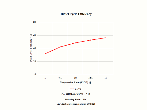
Figure 3 presents the Diesel cycle efficiency as a function of the compression ratio. It should be noted that the compressor inlet temperature is at standard ambient conditions of 298 [K] and 1 [atm] of absolute pressure. The cut off ratio is 3 [/].
Figure 4 presents the Diesel cycle power output as a function of compression and cut off ratio values. It should be noted that the number of revolutions is 60 [1/s] for a given geometry of a four cylinder and four stroke Diesel engine.
One can notice that the Diesel cycle efficiency increases with an increase in the compression ratio. One can notice that the Diesel cycle power output increases with an increase in the compression ratio and that the Diesel cycle power output is greater for higher cut off ratio values.
The general assumptions are as follows:
Working fluid is air. There is no friction. Compression and expansion are isentropic -- there is no entropy change. During heat addition and heat rejection, the air temperature does change. Ideal gas state equation is valid -- pv = RT. Air behaves as a perfect gas -- specific heat has a constant value.
The governing equations are as follows:
T2/T1 = (V1/V2)(ϰ-1)
T3/T4 = (V4/V3)(ϰ-1)
ϰ = cp/cv
pv = RT
wc = cp(T2 - T1)
Wc = cp(T2 - T1)m
we = cp(T3 - T2) + cp - T4)
We = cp(T3 - T2)m + cp(T3 - T4)m
η = 1 - (φ(ϰ–1))/(ϰε(ϰ-1)(φ - 1))
ε = V1/V2
φ = V3/V2
Input data are as follows:
T1 = 298 [K]
p1 = 1 [atm]
ε = 5, 7.5, 10, 12.5 and 15 [/]
φ = 3 and 4 [/]
cp = 1.004 [kJ/kg*K]
ϰ = cp/cv - for air ϰ = 1.4 [/]
The results are as follows:
| Compression
Ratio [/] |
Diesel Cycle Efficiency
[%] |
|---|---|
| Power Output
[kW] |
Compression Ratio
[/] | ||||
|---|---|---|---|---|---|
| Cut Off Ratio
[/] |
5 | 7.5 | 10 | 12.5 | 15 |
The Diesel cycle efficiency increases with an increase in the compression ratio. Also, the Diesel cycle power output increases with an increase in the compression ratio and the Diesel cycle power output is greater for higher cut off ratio values.
Power cycle components/processes analysis
In this section dealing with power cycle components/processes, ideal compression, combustion and expansion operation and their preformance trends are presented.
Compression
In the presented compression analysis, only air is considered as the working fluid behaving as the perfect gas -- specific heat has a constant value. Ideal gas state equation is valid -- pv = RT.
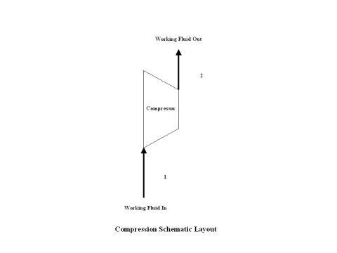
Figure 1 contains a compression schematic layout. Air enters a compressor at point 1, and exits the compressor at point 2. Isentropic compression is considered with no entropy change.
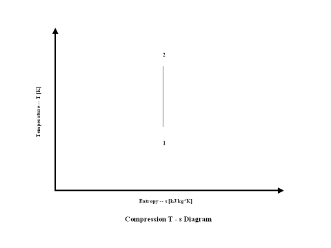
Figure 2 presents a compression entropy vs temperature diagram.
Figure 3 presents compression specific power input requirements for a few typical pressure ratio values. It should be noted that the air enters the compressor at standard ambient conditions of 298 [K] and 1 [atm] of absolute pressure.
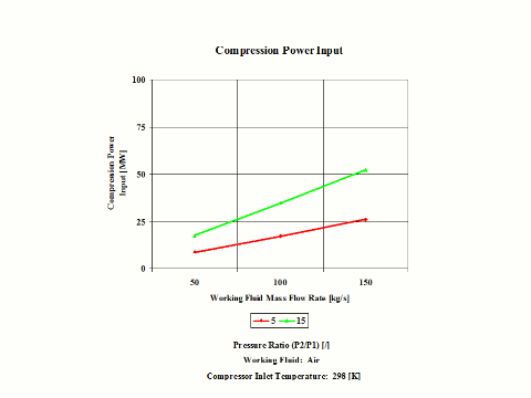
Figure 4 presents compression power input requirements for two typical pressure ratio values and a few different air mass flow rate values.
One can notice that both compression specific power input and power input increase with the pressure ratio. As the air mass flow increases, the compression power input requirements increase too.
The general assumptions are as follows:
Working fluid is air. There is no friction and heat transfer. Compression is isentropic -- there is no entropy change. Ideal gas state equation is valid -- pv = RT. Air behaves as a perfect gas -- specific heat has a constant value.
The governing equations are as follows:
T2/T1 = (p2/p1)(ϰ-1)/ϰ
ϰ = cp/cv
pv = RT
w = cp(T2 - T1)
W = cp(T2 - T1)m
Input data are as follows:
T1 = 298 [K]
p1 = 1 [atm]
p2 = 5, 10 and 15 [atm]
cp = 1.004 [kJ/kg*K]
ϰ = cp/cv - for air ϰ = 1.4 [/]
m = 50, 100 and 150 [kg/s]
The results are as follows:
| Pressure Ratio
[/] |
Specific Power Input
[kW/kg/s] |
|---|---|
| Power Input
[MW] |
Mass Flow Rate
[kg/s] | ||
|---|---|---|---|
| Pressure Ratio
[/] |
50 | 100 | 150 |
Both compression specific power input and power input increase with the pressure ratio. As the air mass flow increases, the compression power input requirements increase too.
Combustion
A combustion analysis for a few typical fuel cases (carbon, hydrogen, sulfur, coal, oil and gas) when the fuel reacts with air at stoichiometric conditions is presented.
Furthermore, in the presented combustion analysis, both fuel and air are at standard inlet combustion conditions of 298 [K] and 1 [atm] of absolute pressure. Furthermore, combustion is complete and with no heat loss.
During the combustion, a large amount of reactants' chemical energy gets released in the form of thermal energy.
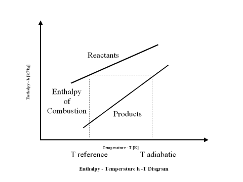
Enthalpy of combustion (HHV) is the difference between the reactants enthalpy value minus the combustion products enthalpy value at the standard reference temperature, which is 298 [K].
When the reactants enthalpy value is equal to the combustion products enthalpy value, one can calculate the combustion products flame temperature (adiabatic temperature).
The plot in Figure 1 depicts the reactants and combustion products enthalpy value change with an increase in the temperature.
Physical properties for both reactants and combustion products are very important and need to be known in order to carry out successful combustion calculations.
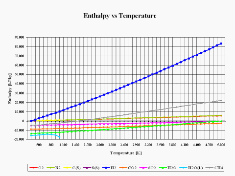
The plot in Figure 2 depicts how the reactants and combustion products species enthalpy values change with the temperature. The physical properties provided in this plot come from the JANAF Thermochemical Data - Tables, 1970.
It is interesting to note that the enthalpy value for basic combustion elements such as carbon (C), hydrogen (H2), sulfur (S), oxygen (O2) and nitrogen (N2) is equal to zero at the standard combustion conditions of 298 [K] and 1 [atm].
Also, it should be mentioned that for ideal gas species, the enthalpy value is only dependent on the temperature.
In addition to knowing the reactants and combustion products physical properties, for any kind of combustion analysis and calculations, it is important to know both fuel and oxidant compositions.
For solid and liquid type fuels, the fuel composition is given on the weight basis for a unit mass amount. For the gas type fuels, the fuel composition is provided on the mole/volume basis for a unit volume amount. In this analysis, methane (CH4) is the only gas fuel considered. In order to keep the combustion analysis simple and straightforward, the CH4 composition is provided on the weight basis. Oxidant composition is usually given on the mole/volume basis.
Table 1 provides the fuel composition.
| C | H | S | N | O | H2O | CH4 | |
|---|---|---|---|---|---|---|---|
| 1.000 | 0.000 | 0.000 | 0.000 | 0.000 | 0.000 | ||
| 0.000 | 1.000 | 0.000 | 0.000 | 0.000 | 0.000 | ||
| 0.000 | 0.000 | 1.000 | 0.000 | 0.000 | 0.000 | ||
| 0.780 | 0.050 | 0.030 | 0.040 | 0.080 | 0.020 | ||
| 0.860 | 0.140 | 0.000 | 0.000 | 0.000 | 0.000 | ||
| 1.000 |
Table 2 provides the standard air composition.
| N [kg/kg] |
O [kg/kg] |
N2 [kmol/kmol] |
O2 [kmol/kmol] | |
|---|---|---|---|---|
Again, in this combustion analysis, only the stoichiometric combustion is analyzed. Results of such analysis are provided, including a combustion products composition on weight and mole/volume basis, a flame temperature, a stoichiometric ratio and a higher heating value (HHV).
Table 3 provides the combustion products composition on the weight basis.
| CO2 | H2O | SO2 | N2 | O2 | |
|---|---|---|---|---|---|
| 0.295 | 0.000 | 0.000 | 0.705 | 0.000 | |
| 0.000 | 0.255 | 0.000 | 0.745 | 0.000 | |
| 0.000 | 0.000 | 0.378 | 0.622 | 0.000 | |
| 0.249 | 0.041 | 0.005 | 0.705 | 0.000 | |
| 0.202 | 0.080 | 0.000 | 0.718 | 0.000 | |
| 0.151 | 0.124 | 0.000 | 0.725 | 0.000 |
Table 4 provides the combustion products composition on the volume basis.
| CO2 | H2O | SO2 | N2 | O2 | |
|---|---|---|---|---|---|
| 0.210 | 0.000 | 0.000 | 0.790 | 0.000 | |
| 0.000 | 0.347 | 0.000 | 0.653 | 0.000 | |
| 0.000 | 0.000 | 0.210 | 0.789 | 0.000 | |
| 0.170 | 0.068 | 0.002 | 0.759 | 0.000 | |
| 0.132 | 0.129 | 0.000 | 0.739 | 0.000 | |
| 0.095 | 0.190 | 0.000 | 0.715 | 0.000 |
When considering coal, oil and gas as the fuel, coal has the largest amount of CO2 in the combustion products on both weight and mole basis.
Table 5 provides the combustion products flame temperature, stoichiometric ratio and the fuel higher heating value.
[K] |
(See Note Below!) |
[kJ/kg] | |
|---|---|---|---|
| Note: Stoichiometric ratio is the mass of air required for complete combustion of a unit mass of fuel. Thus, 1 [kg] of carbon fuel requires 11.444 [kg] of air for complete, ideal combustion. | |||
Stoichiometric ratio is the mass of air required for complete combustion of a unit mass of fuel. Thus, 1 [kg] of carbon fuel requires 11.433 [kg] of air for complete, ideal combustion.
Today, global warming is becoming more evident and it is being said that it is primarily caused by CO2 emissions. A detailed combustion analysis, as it is provided here, can be very useful in determining different fuel and technology scenarios that would result in the reduction of current CO2 emissions.
The general assumptions:
Both fuel and air are at standard inlet combustion conditions of 298 [K] and 1 [atm] of absolute pressure.
Furthermore, combustion is complete and with no heat loss.
The governing equations are as follows:
Enthalpy of combustion (HHV) is the difference between the reactants enthalpy value minus the combustion products enthalpy value at the standard reference temperature, which is 298 [K].
When the reactants enthalpy value is equal to the combustion products enthalpy value, one can calculate the combustion products flame temperature (adiabatic temperature).
Input data are as follows:
| C | H | S | N | O | H2O | CH4 | |
|---|---|---|---|---|---|---|---|
| 1.000 | 0.000 | 0.000 | 0.000 | 0.000 | 0.000 | ||
| 0.000 | 1.000 | 0.000 | 0.000 | 0.000 | 0.000 | ||
| 0.000 | 0.000 | 1.000 | 0.000 | 0.000 | 0.000 | ||
| 0.780 | 0.050 | 0.030 | 0.040 | 0.080 | 0.020 | ||
| 0.860 | 0.140 | 0.000 | 0.000 | 0.000 | 0.000 | ||
| 1.000 |
| N [kg/kg] |
O [kg/kg] |
N2 [kmol/kmol] |
O2 [kmol/kmol] | |
|---|---|---|---|---|
The results are as follows:
| CO2 | H2O | SO2 | N2 | O2 | |
|---|---|---|---|---|---|
| 0.295 | 0.000 | 0.000 | 0.705 | 0.000 | |
| 0.000 | 0.255 | 0.000 | 0.745 | 0.000 | |
| 0.000 | 0.000 | 0.378 | 0.622 | 0.000 | |
| 0.249 | 0.041 | 0.005 | 0.705 | 0.000 | |
| 0.202 | 0.080 | 0.000 | 0.718 | 0.000 | |
| 0.151 | 0.124 | 0.000 | 0.725 | 0.000 |
| CO2 | H2O | SO2 | N2 | O2 | |
|---|---|---|---|---|---|
| 0.210 | 0.000 | 0.000 | 0.790 | 0.000 | |
| 0.000 | 0.347 | 0.000 | 0.653 | 0.000 | |
| 0.000 | 0.000 | 0.210 | 0.789 | 0.000 | |
| 0.170 | 0.068 | 0.002 | 0.759 | 0.000 | |
| 0.132 | 0.129 | 0.000 | 0.739 | 0.000 | |
| 0.095 | 0.190 | 0.000 | 0.715 | 0.000 |
[K] |
(See Note Below!) |
[kJ/kg] | |
|---|---|---|---|
| Note: Stoichiometric ratio is the mass of air required for complete combustion of a unit mass of fuel. Thus, 1 [kg] of carbon fuel requires 11.444 [kg] of air for complete, ideal combustion. | |||
Expansion
In the presented expansion analysis, only air is considered as the working fluid behaving as the perfect gas -- specific heat has a constant value. Ideal gas state equation is valid -- pv = RT.
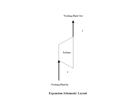
Figure 1 contains an expansion schematic layout. Air enters a turbine at point 1, and exits the turbine at point 2. Isentropic expansion is considered with no entropy change.
Figure 2 presents an expansion entropy vs temperature diagram.
Figure 3 presents expansion specific power output values for a few typical pressure ratio values. It should be noted that the air enters the turbine at the temperature of 1,500 [K] and the turbine exhaust pressure is always equal to the standard ambient pressure -- 1 [atm] of absolute pressure.
Figure 4 presents expansion power output values for two typical pressure ratio values and a few different air mass flow rate values.
One can notice that both expansion specific power output and power output increase with the pressure ratio. As the air mass flow increases, the expansion power output values increase too.
The general assumptions are as follows:
Working fluid is air. There is no friction and heat transfer. Expansion is isentropic -- there is no entropy change. Ideal gas state equation is valid -- pv = RT. Air behaves as a perfect gas -- specific heat has a constant value.
The governing equations are as follows:
T1/T2 = (p1/p2)(ϰ-1)/ϰ
ϰ = cp/cv
pv = RT
w = cp(T1 - T2)
W = cp(T1 - T2)m
Input data are as follows:
T1 = 1,500 [K]
p1 = 5, 10 and 15 [atm]
p2 = 1 [atm]
cp = 1.004 [kJ/kg*K]
ϰ = cp/cv - for air ϰ = 1.4 [/]
m = 50, 100 and 150 [kg/s]
The results are as follows:
| Pressure Ratio
[/] |
Specific Power Output
[kW/kg/s] |
|---|---|
| Power Output
[MW] |
Mass Flow Rate
[kg/s] | ||
|---|---|---|---|
| Pressure Ratio
[/] |
50 | 100 | 150 |
Both expansion specific power output and power output increase with the pressure ratio. As the air mass flow increases, the expansion power output values increase too.
Compressible flow analysis
In this section dealing with compressible flow, ideal and isentropic operation of nozzle, diffuser and thrust and their preformance trends are presented.
Nozzle
In the presented nozzle analysis, only air is considered as the working fluid behaving as the perfect gas -- specific heat has a constant value. Ideal gas state equation is valid -- pv = RT.
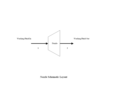
Figure 1 contains a nozzle schematic layout. Air enters a nozzle at point 1, and exits the nozzle at point 2. Isentropic expansion is considered with no entropy change.
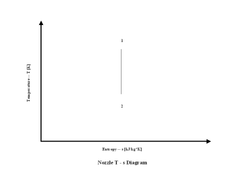
Figure 2 presents a nozzle entropy vs temperature diagram.
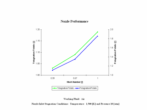
Figure 3 presents nozzle performance -- stagnation over static temperature and pressure values -- as a function of the Mach Number. Only subsonic nozzle operation is considered. It should be noted that air enters the nozzle at the stagnation conditions of 1,500 [K] and 10 [atm] of absolute pressure.
One can notice that nozzle stagnation over static temperature and pressure ratio values increase with an increase of the Mach Number.
The general assumptions are as follows:
Working fluid is air. There is no friction and heat transfer. Expansion is isentropic -- there is no entropy change. Ideal gas state equation is valid -- pv = RT. Air behaves as a perfect gas -- specific heat has a constant value.
The governing equations are as follows:
Tt /T = (1 + M2(ϰ - 1)/2)
pt/p = (1 + M2(ϰ - 1)/2)ϰ/(ϰ-1)
Tt/T = (pt/p)(ϰ-1)/ϰ
v = (2cp(Tt - T))1/2
vs = (ϰRT)1/2
M = v/vs
ϰ = cp/cv
pv = RT
Input data are as follows:
T1 = 1,500 [K]
p1 = 10 [atm]
cp = 1.004 [kJ/kg*K]
ϰ = cp/cv - for air ϰ = 1.4 [/]
M = 0.39, 0.67 and 1 [/]
The results are as follows:
| Mach Number
[/] |
Temperature Ratio
[/] |
Pressure Ratio
[/] |
|---|---|---|
Nozzle stagnation over static temperature and pressure ratio values increase with an increase of the Mach Number.
Diffuser
In the presented diffuser analysis, only air is considered as the working fluid behaving as the perfect gas -- specific heat has a constant value. Ideal gas state equation is valid -- pv = RT.
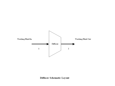
Figure 1 contains a diffuser schematic layout. Air enters a diffuser at point 1, and exits the diffuser at point 2. Working fluid inlet velocity gets reduced to zero resulting in the stagnation temperature and pressure increase. Isentropic process is considered with no entropy change.
Figure 2 presents a diffuser entropy vs temperature diagram.
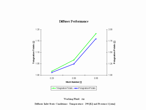
Figure 3 presents diffuser performance -- stagnation over static temperature and pressure values -- as a function of the Mach Number. Only subsonic diffuser operation is considered. It should be noted that the air enters the diffuser at the static conditions of 298 [K] and 1 [atm] of absolute pressure.
One can notice that diffuser stagnation over static temperature and pressure ratio values increase with an increase of the Mach Number.
The genaral assumptions are as follows:
Working fluid is air. There is no friction and heat transfer. Isentropic process -- there is no entropy change. Ideal gas state equation is valid -- pv = RT. Air behaves as a perfect gas -- specific heat has a constant value.
The governing equations are as follows:
Tt/T = (1 + M2(ϰ - 1)/2)
pt/p = (1 + M2(ϰ - 1)/2)ϰ/(ϰ-1)
Tt/T = (pt/p)(ϰ-1)/ϰ
Tt = T + v2/(2cp)
vs = (ϰRT)1/2
M = v/vs
ϰ = cp/cv
pv = RT
Input data are as follows:
T1 = 298 [K]
p1 = 1 [atm]
cp = 1.004 [kJ/kg*K]
ϰ = cp/cv - for air ϰ = 1.4 [/]
M = 0.29, 0.58 and 0.95 [/]
The results are as follows:
| Mach Number
[/] |
Temperature Ratio
[/] |
Pressure Ratio
[/] |
|---|---|---|
Diffuser stagnation over static temperature and pressure ratio values increase with an increase of the Mach Number.
Thrust
In the presented thrust analysis, only air is considered as the working fluid behaving as the perfect gas -- specific heat has a constant value. Ideal gas state equation is valid -- pv = RT.
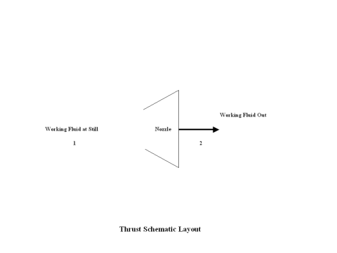
Figure 1 contains a thrust schematic layout. Air enters a nozzle at point 1, and exits the nozzle at point 2. Isentropic expansion is considered with no entropy change.
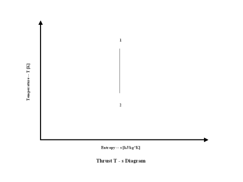
Figure 2 presents a thrust entropy vs temperature diagram.
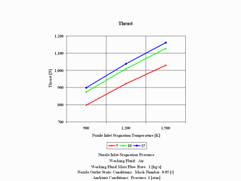
Figure 3 presents thrust performance as a function of the nozzle inlet stagnation temperature and pressure for a few fixed values such as: working fluid mass flow rate, nozzle outlet Mach Number and ambient pressure. Only subsonic nozzle operation is considered.
One can notice that thrust values increase with an increase of the inlet stagnation temperature and pressure.
The general assumptions are as follows:
Working fluid is air. There is no friction and heat transfer. Expansion is isentropic -- there is no entropy change. Ideal gas state equation is valid -- pv = RT. Air behaves as a perfect gas -- specific heat has a constant value.
The governing equations are as follows:
Tt/T = (1 + M2(ϰ - 1)/2)
pt/p = (1 + M2(ϰ - 1)/2)ϰ/(ϰ-1)
Tt/T = (pt/p)(ϰ -1)/k
v = (2cp(Tt – T))1/2
vs = (ϰRT)1/2
M = v/vs
ϰ = cp/cv
pv = RT
Thrust = vm + (p - pa)A
Input data are as follows:
T1 = 900, 1,200 and 1,500 [K]
p1 = 5, 10 and 15 [atm]
cp = 1.004 [kJ/kg*K]
ϰ = cp/cv - for air ϰ = 1.4 [/]
m = 1 [kg/s]
M = 0.85 [/]
pa = 1 [atm]
The results are as follows:
| Thrust
[N] |
Inlet Stagnation Temperature
[K] | ||
|---|---|---|---|
| Inlet Stagnation Pressure
[atm] |
900 | 1,200 | 1,500 |
Thrust values increase with an increase of the inlet stagnation temperature and pressure.
References
JANAF Thermochemical Data - Tables, 1970

