Centrifugal force: Difference between revisions
imported>John R. Brews (→Centrifugal couple: caption) |
imported>John R. Brews (→Centrifugal couple: explain application to tire) |
||
| Line 101: | Line 101: | ||
|url=http://books.google.com/books?id=OvWyD3sREzgC&pg=PA112 | |url=http://books.google.com/books?id=OvWyD3sREzgC&pg=PA112 | ||
|page=112 | |page=112 | ||
}}</ref> The figure shows a rotating shaft unbalanced by two identical attached weights causing a counterclockwise centrifugal couple ''Cd'' that must be resisted by a clockwise couple ''Fℓ'' = ''Cd'' exerted by the bearings. The figure is drawn from the viewpoint of a frame rotating with the shaft, hence the centrifugal forces. To avoid the stress upon the bearings caused by the centrifugal couple, counterbalancing weights must be added. The unbalancing weights are an idealization, of course. For example, | }}</ref> The figure shows a rotating shaft unbalanced by two identical attached weights causing a counterclockwise centrifugal couple ''Cd'' that must be resisted by a clockwise couple ''Fℓ'' = ''Cd'' exerted by the bearings. The figure is drawn from the viewpoint of a frame rotating with the shaft, hence the centrifugal forces. To avoid the stress upon the bearings caused by the centrifugal couple, counterbalancing weights must be added. The unbalancing weights are an idealization, of course. For example, suppose the rod is interpreted as the axle of an automobile tire, and the two weights represent asymmetry in the weight distribution of the of the tire. That is an idealization of the real imbalance that is due to imperfections of manufacture that make the tire composition inhomogeneous. | ||
==Notes== | ==Notes== | ||
<references/> | <references/> | ||
Revision as of 10:39, 17 February 2011
Centrifugal force (from Latin centrum "center" and fugere "to flee") refers to an outward force experienced by a body on a curved path that is directed away from the center of curvature. Such a force is experienced in a reference frame attached to the body, which (because the body is not in a uniform straight-line motion) is an accelerating reference frame, not an inertial reference frame. Such a body also may experience other forces due to its acceleration, namely the Coriolis force and the Euler force.
Reference frames
Newton's laws of motion are expressed for observations made in an inertial frame of reference, commonly referred to as any frame of reference that is in straight-line motion at constant speed relative to the "fixed stars", an historical reference taken today to refer to the entire universe. However, everyday experience does not take place in such a reference frame. For example, we live upon planet Earth, which rotates about its axis (an accelerated motion), orbits the Sun (another accelerated motion), and moves with the Milky Way (still another accelerated motion). These motions are slight, although they do affect matters such as aiming artillery pieces and plotting transoceanic air flights. More visceral examples of everyday experience of non-inertial frames are roller coaster rides and simply turning a sharp corner in a car. In these last examples we are immediately aware of forces upon us due to our motion, and we interpret these motions from our own viewpoint, not that of an impartial observer attached to the universe.
The question then arises as to how to connect these experiences in accelerating frames with Newton's laws that are not formulated for such situations. The answer lies in the introduction of inertial forces, which are forces observed in the accelerating reference frame, due to its motion, but are not forces recognized in an inertial frame. These inertial forces are included in Newton's laws of motion, and with their inclusion Newton's laws work just as they would in an inertial frame. Centrifugal force is one of these inertial forces, the other two being the Coriolis force and the Euler force.
The way inertial forces work is illustrated below by a few examples.
Rotating spheres
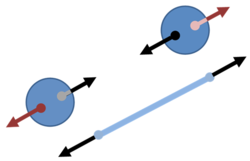
Consider two identical balls isolated in space, but connected by a rope. We ignore any effects of gravity. We observe the tension in the rope, for example, by placing a spring in the center of the rope and measuring its stretch when the rope is under tension. We sit at the center of the rope and inquire whether the two balls are rotating about us.
This thought experiment was devised by Newton, who wanted to explore the question of whether we could discover that the balls were rotating even though we had no point of reference from which to infer that rotation was underway. He concluded that an observed tension in the rope would allow us to infer that the balls are rotating:[1][2]
| ‘ | We have some arguments to guide us, partly from the apparent motions, which are the differences of the true motions; partly from the forces, which are the causes and effects of the true motions. For instance, if two globes kept at a given distance one from the other, by means of a cord that connects them, were revolved about their common center of gravity; we might, from the tension of the cord, discover the endeavor of the globes to recede from the axis of their motion. ... And thus we might find both the quantity and the determination of this circular motion, even in an immense vacuum, where there was nothing external or sensible with which the globes could be compared. | ’ |
—Isaac Newton, Principia: Definitions – Scholium; 1729 Andrew Motte translation | ||
It is clear that the tension in the rope, as indicated by the stretch of the spring, is an incontrovertible observation that any observer would see, regardless of whether they were stationary or rotating with the balls.
Let us now look at this tension from the viewpoint of the inertial observers: they see the balls rotating with an angular rate of (say) ω radians/s. That means the balls have a speed of v = ωR where 2R is the separation of the centers of the balls. Their circular motion means that each ball is subject to an inward centripetal force provided by the tension in the rope, of magnitude FT = mv2/R = mRω2, and the measured stretch of the spring reflects exactly this force.
Next, let's look at things from the viewpoint of the rotating observers sitting at the center of the rope. They see the balls as stationary, because they are rotating with them. Because they rotate at the same rate as the spheres, they are said to be in a co-rotating frame. But they also see the stretched spring. Despite the tension from the stretched string, the balls do not move, so they are subject to no net force. The rotating observers succeed in using Newton's laws to explain the tension despite no motion, and to explain no motion despite the tension because, in their rotating frame, they experience a centrifugal force, an outward force radiating from their center position that affects all bodies they observe (including themselves if they move off-center). This centrifugal radially outward force on objects at distance R is of magnitude mRω2, but of course, these rotating observers simply see that this is the tension in the spring, and they cannot calculate its magnitude from scratch because they cannot measure the rotational rate ω.
However, if they are quite sophisticated, the rotating observers will notice that the centrifugal force they observe on every object they measure has some peculiar properties not shared by forces such as gravitational, electrical, or nuclear forces. In particular, it has no observable source such as a mass, a charge or an atomic nucleus, like other physical forces, and appears to become larger the further you go from its radiating center, instead of weakening with distance like other forces. So they might conclude that this is an inertial force and try to explain their observations based upon their frame seen as a rotating frame, and calculate their rate of rotation using the measured tension and the formula FT = mRω2. If they did that, then their calculations would be mapped into an inertial frame, and they would analyze the situation the same way as an inertial observer. They then would use centripetal force instead of centrifugal force in their calculations, and their inferred rate of rotation ω.
But as they move about in their rotating frame, their immediate visceral experience of the centrifugal force is a real part of everyday life, whatever the frame they use for theoretical calculations. In particular, the centrifugal force leads to real tension in the rope, despite the fact that nothing is moving. Likewise, when you corner a car, centrifugal force rams you into the door, a real effect from your perspective in your very own wildly accelerating frame of reference, even though the imperturbable inertial observer explains this occurrence as your need for a push from the car to keep you turning with the car instead of continuing on a straight path.
Whirling table
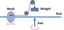
An apparatus called a "whirling table" consists of a rod that can be whirled about an axis, causing a bead to slide on the rod under the influence of centrifugal force.[3] A cord ties a weight to the sliding bead.
In a frame co-rotating with the rod, equilibrium is achieved when the inward force on the bead due to the weight exactly counterbalances the outward centrifugal force upon the bead. By observing changes in the equilibrium balancing distance for a given weight, or the variation of the weight at a fixed distance, the centrifugal force can be measured under changing conditions and used to infer the rate of rotation, which is not observable directly in a co-rotating frame.
From the viewpoint of an inertial (non-rotating) frame of reference, equilibrium results when the bead is positioned in the particular circular orbit for which the weight provides the correct centripetal force. By observing how the equilibrium balancing distance varies with the weight and the speed of rotation, the centripetal force can be measured as a function of the rate of rotation and the distance of the bead from the center of rotation.
Rotating liquid

Force diagram for an element of water surface in co-rotating frame. Top: Radial section and selected point on water surface; the water, the co-rotating frame, and the radial section share a constant angular rate of rotation given by the vector Ω. Bottom: Force diagram at selected point on surface. The slope of the surface adjusts to make all three forces sum to zero.
The shape of the surface of a rotating liquid in a bucket can be determined using Newton's laws for the various forces on an element of the surface. For example, see Knudsen and Hjorth.[4] The figure sets up the analysis in the co-rotating frame where the water appears stationary. The height of the water h = h(r) is a function of the radial distance r from the axis of rotation Ω, and the aim is to determine this function. An element of water volume on the surface is shown to be subject to three forces: the vertical force due to gravity Fg, the horizontal, radially outward centrifugal force FCfgl, and the force normal to the surface of the water Fn due to the rest of the water surrounding the selected element of surface. The force due to surrounding water is known to be normal to the surface of the water because a liquid in equilibrium cannot support shear stresses.[5] To quote Anthony and Brackett:[6]
| ‘ | The surface of a fluid of uniform density…, if at rest, is everywhere perpendicular to the lines of force; for if this were not so, the force at a point on the surface could be resolved into two components, one perpendicular and the other tangent to the surface. But from the nature of a fluid, the tangential force would set up a motion of the fluid, which is contrary to the statement that the fluid is at rest. | ’ |
—William Arnold Anthony & Cyrus Fogg Brackett: Elementary Text-book of Physics, p. 127 | ||
Moreover, because the element of water does not move, the sum of all three forces must be zero. To sum to zero, the force of the water must point oppositely to the sum of the centrifugal and gravity forces, which means the surface of the water must adjust so its normal points in this direction. (A very similar problem is the design of a banked turn, where the slope of the turn is set so a car will not slide off the road. The analogy in the case of rotating bucket is that the element of water surface will "slide" up or down the surface unless the normal to the surface aligns with the vector resultant formed by the vector addition Fg + FCfgl.)
As r increases, the centrifugal force increases according to the relation (the equations are written per unit mass):
where Ω is the constant rate of rotation of the water. (In the co-rotating frame, the rate of rotation Ω cannot be measured directly because there is no rotation; but the centrifugal force can be seen to increase with r, and Ω is taken as an empirical proportionality factor.) The gravitational force is unchanged at
where g is the acceleration due to gravity. These two forces add to make a resultant at an angle φ from the vertical given by
which clearly becomes larger as r increases. To insure that this resultant is normal to the surface of the water, and therefore can be effectively nulled by the force of the water beneath, the normal to the surface must have the same angle, that is,
leading to the ordinary differential equation for the shape of the surface:
or, integrating:
where h(0) is the height of the water at r = 0. In words, the surface of the water is parabolic in its dependence upon the radius.
Of course, it is not possible for the observers in the co-rotating frame to measure directly the angular rate Ω. However, they can observe the parabolic surface, and if they adopt the view that the centrifugal force is due to rotation, they can determine their rate of rotation by measuring the curvature of the water's surface.
Skywriter
- See also: Centripetal force#Banked turn
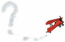
What is the viewpoint of an airplane pilot engaged in skywriting? The plane's path is the smoky trail left behind, and progress can be registered as the distance s from the start of the trail to the plane's present position. The speed of the plane is v = ds / dt and the curvature of the path is measured by the osculating circle of radius ρ that is tangent to the path. For the inertial observer watching from the ground, the plane at any instant is executing circular motion about its (instantaneous) center of curvature, and so is subject to a centripetal force v2 / ρ acting radially inward toward this center of curvature.[7] To maintain trajectory, this centripetal force is provided by banking the airplane, generating a lift that provides this centripetal force. According to the pilot, however, the plane is stationary, but subject to a centrifugal force outward from the instantaneous center of curvature with a magnitude v2 / ρ.[8] To maintain trajectory, this centrifugal force is combated by banking the airplane, generating a lift to counteract the centrifugal force, thereby maintaining the plane in its equilibrium motionless position.[9]
Centrifugal couple
The balancing of automobile tires or rotating shafts involves an example of centrifugal force referred to as a centrifugal couple.[10] The figure shows a rotating shaft unbalanced by two identical attached weights causing a counterclockwise centrifugal couple Cd that must be resisted by a clockwise couple Fℓ = Cd exerted by the bearings. The figure is drawn from the viewpoint of a frame rotating with the shaft, hence the centrifugal forces. To avoid the stress upon the bearings caused by the centrifugal couple, counterbalancing weights must be added. The unbalancing weights are an idealization, of course. For example, suppose the rod is interpreted as the axle of an automobile tire, and the two weights represent asymmetry in the weight distribution of the of the tire. That is an idealization of the real imbalance that is due to imperfections of manufacture that make the tire composition inhomogeneous.
Notes
- ↑ Isaac Newton (Andrew Motte translation of 1729). Definitions: Scholium (last paragraph). The Principia. Retrieved on 2011-02-15.
- ↑ Max Born (1962). Einstein's Theory of Relativity. Courier Dover Publications, p. 80. ISBN 0486607690.
- ↑ Dionysius Lardner (1877). Mechanics. Oxford University Press, p. 150.
- ↑ Jens M. Knudsen, Poul G. Hjorth (2000). Elements of Newtonian Mechanics, 3rd Edition. Springer, p. 143. ISBN 354067652X,.
- ↑ Lawrence S. Lerner (1997). Physics for Scientists and Engineers. Jones & Bartlett, p. 404. ISBN 0867204796.
- ↑ William Arnold Anthony & Cyrus Fogg Brackett (1884). Elementary Text-book of Physics. Wiley, p. 127.
- ↑ Donald A. Danielson (2003). Vectors and Tensors in Engineering and Physics. Westview Press. ISBN 0813340802.
- ↑ Denison Olmsted & Ebenezer Strong Snell (1861). An Introduction to Natural Philosophy. Collins & Brother.
- ↑ As seen by the inertial observer, the plane also may accelerate along its path (dv / dt = d2s / dt2 > 0). For the pilot this acceleration introduces another fictitious force: the Euler force.
- ↑ Gaetano Lanza (2009). Dynamics of Machinery, Reprint of 1911. BiblioBazaar. ISBN 1103197215.


