User:John R. Brews/Images: Difference between revisions
Jump to navigation
Jump to search
imported>John R. Brews |
No edit summary |
||
| (32 intermediate revisions by one other user not shown) | |||
| Line 1: | Line 1: | ||
{{AccountNotLive}} | |||
{{DEFAULTSORT:Brews, John R.}} | {{DEFAULTSORT:Brews, John R.}} | ||
{{TOC|right}} | {{TOC|right}} | ||
| Line 34: | Line 35: | ||
==Circuits== | ==Circuits== | ||
{{Gallery-mixed | {{Gallery-mixed | ||
|caption= | |caption=Current sources | ||
|width=200 | |width=200 | ||
|lines=5 | |lines=5 | ||
| Line 45: | Line 46: | ||
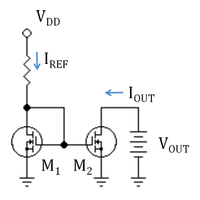
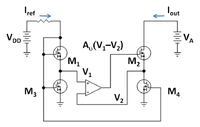
|Wide-swing MOSFET mirror.PNG| MOSFET version of wide-swing current mirror; M<sub>1</sub> and M<sub>2</sub> are in active mode | |Wide-swing MOSFET mirror.PNG| MOSFET version of wide-swing current mirror; M<sub>1</sub> and M<sub>2</sub> are in active mode | ||
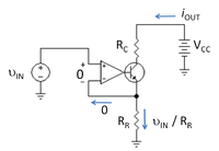
|Current sink.PNG|Operational-amplifier based current sink. Because the op amp is modeled as a nullor, op amp input variables are zero regardless of the values for its output variables. | |Current sink.PNG|Operational-amplifier based current sink. Because the op amp is modeled as a nullor, op amp input variables are zero regardless of the values for its output variables. | ||
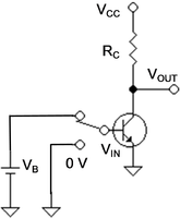
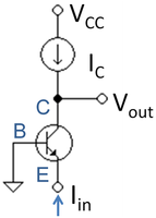
|Bipolar inverter.PNG|A digital inverter circuit using a bipolar transistor. | |||
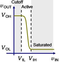
|Transfer characteristic of bipolar inverter.PNG|Transfer characteristic of bipolar inverter showing modes. | |||
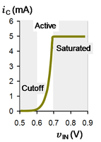
|Current in bipolar inverter.PNG|Collector current ''vs.'' input voltage for a bipolar inverter with ''V<sub>CC</sub>''<nowiki>=</nowiki>5V and ''R<sub>C</sub>''<nowiki>=</nowiki>1kΩ. | |||
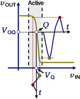
|Amplifier input and output.PNG|Input and output signals for bipolar inverter used as an amplifier. | |||
|Two-port with Thevenin driver.PNG| Two-port network with symbol definitions. | |Two-port with Thevenin driver.PNG| Two-port network with symbol definitions. | ||
|Z-equivalent two-port.PNG| Z-equivalent two port showing independent variables ''I<sub>1</sub>'' and ''I<sub>2</sub>''. | |Z-equivalent two-port.PNG| Z-equivalent two port showing independent variables ''I<sub>1</sub>'' and ''I<sub>2</sub>''. | ||
| Line 50: | Line 55: | ||
|H-equivalent two-port.PNG|H-equivalent two-port showing independent variables | |H-equivalent two-port.PNG|H-equivalent two-port showing independent variables | ||
|G-equivalent two-port.PNG| G-equivalent two-port showing independent variables | |G-equivalent two-port.PNG| G-equivalent two-port showing independent variables | ||
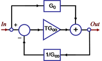
|Block diagram asymptotic gain.PNG|Block diagram for asymptotic gain model | |||
|Signal-flow graph for asymptotic gain model.PNG|Possible signal-flow graph for the asymptotic gain model | |||
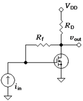
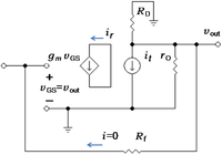
|MOSFET Transresistance amplifier.PNG| MOSFET transresistance feedback amplifier. | |||
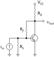
|Bipolar transresistance feedback amplifier.PNG| Collector-to-base biased bipolar amplifier. | |||
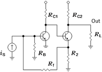
|Shunt-series feedback amplifier.PNG|Two-transistor feedback amplifier; any source impedance ''R<sub>S</sub>'' is lumped in with the base resistor ''R<sub>B</sub>''. | |||
}} | |||
{{Gallery-mixed | |||
|caption=Small-signal circuits | |||
|width=200 | |||
|lines=5 | |||
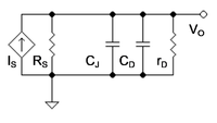
|PN-diode small-signal circuit2.PNG|Small-signal circuit for ''pn-''diode driven by a current signal represented as a [[Norton's theorem|Norton source]]. | |||
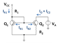
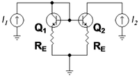
|Bipolar current mirror with emitter resistors.PNG| Bipolar current mirror with emitter resistors | |Bipolar current mirror with emitter resistors.PNG| Bipolar current mirror with emitter resistors | ||
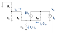
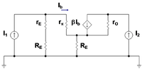
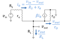
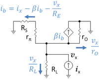
|Small-signal circuit for bipolar mirror.PNG| Small-signal circuit for bipolar current mirror | |Small-signal circuit for bipolar mirror.PNG| Small-signal circuit for bipolar current mirror | ||
| Line 70: | Line 86: | ||
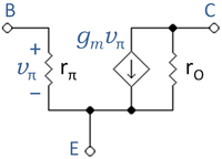
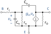
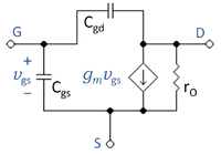
|MOSFET hybrid-pi with capactances.PNG|Simplified, three-terminal MOSFET hybrid-pi model. | |MOSFET hybrid-pi with capactances.PNG|Simplified, three-terminal MOSFET hybrid-pi model. | ||
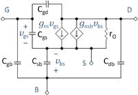
|MOSFET four-terminal hybrid-pi circuit.PNG|Four-terminal small-signal MOSFET circuit. | |MOSFET four-terminal hybrid-pi circuit.PNG|Four-terminal small-signal MOSFET circuit. | ||
|Miller effect.PNG|Miller effect: These two circuits are equivalent. | |||
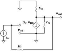
|Small-signal transresistance amplifier.PNG| Small-signal circuit for transresistance amplifier | |||
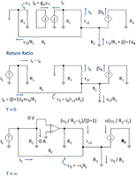
|Return ratio.PNG|Small-signal circuit with return path broken and test current ''i<sub>t</sub>'' driving amplifier at the break. | |||
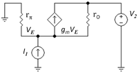
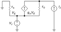
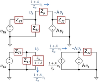
|Using return ratio.PNG|Three small-signal schematics used to discuss the asymptotic gain model | |||
}} | |||
{{Gallery-mixed | |||
|caption=Return ratio | |||
|width=500 | |||
|lines=5 | |||
|Inserting source for return ratio.PNG|''Left'' - small-signal circuit corresponding to bipolar amplifier; ''Center'' - inserting independent source and marking leads to be cut; ''Right'' - cutting the dependent source free and short-circuiting broken leads. | |||
}} | |||
{{Gallery-mixed | |||
|caption=Amplifiers | |||
|width=200 | |||
|lines=5 | |||
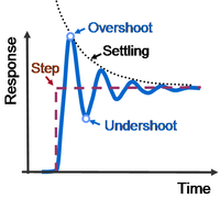
|Aspects of step response.PNG|Some terms used to describe step response in time domain. | |||
|Negative feedback amplifier.PNG|Ideal negative feedback model; open loop gain is ''A''<sub>OL</sub> and feedback factor is β. | |||
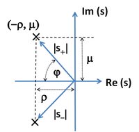
|Conjugate poles.PNG|Conjugate pole locations for step response of two-pole feedback amplifier. | |||
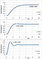
|Step response of negative feedback amplifier.PNG| Step-response of a linear two-pole feedback amplifier. | |||
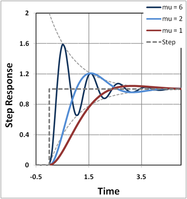
|Overshoot control.PNG|Step response for three values of time constant ratio. | |||
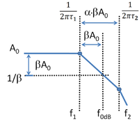
|Gain Bode plot for two-pole amplifier.PNG|Bode gain plot to find phase margin of two-pole amplifier. | |||
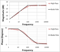
|High-pass amplifier Bode plot.PNG|The Bode plot for a first-order (one-pole) [[highpass filter]] | |||
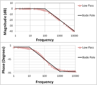
|Low-pass amplifier Bode plot.PNG|The Bode plot for a first-order (one-pole) [[lowpass filter]] | |||
|Bode plot for pole and zero.PNG| Bode magnitude plot for zero and for low-pass pole | |||
|Bode phase plot for pole and zero.PNG|Bode phase plot for zero and for low-pass pole | |||
|Superposed Bode plots for pole and zero.PNG|Bode magnitude plot for pole-zero combination; the location of the zero is ten times higher than in above figures | |||
|Superposed Bode phase plots for pole and zero.PNG|Bode phase plot for pole-zero combination; the location of the zero is ten times higher than in above figures | |||
|Open and closed loop gain.PNG|Gain of feedback amplifier ''A''<sub>FB</sub> in dB and corresponding open-loop amplifier ''A''<sub>OL</sub>. | |||
|Open and closed loop phase.PNG|Phase of feedback amplifier ''°A''<sub>FB</sub> in degrees and corresponding open-loop amplifier ''°A''<sub>OL</sub>. | |||
|Gain margin.PNG|Gain of feedback amplifier ''A''<sub>FB</sub> in dB and corresponding open-loop amplifier ''A''<sub>OL</sub>. | |||
|Phase margin.PNG|Phase of feedback amplifier ''A''<sub>FB</sub> in degrees and corresponding open-loop amplifier ''A''<sub>OL</sub>. | |||
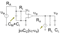
|Pole splitting example.PNG| Operational amplifier with compensation capacitor ''C<sub>C</sub>'' between input and output to cause pole splitting. | |||
|Pole splitting with Miller transformation.PNG|Operational amplifier with compensation capacitor transformed using [[Miller effect|Miller's theorem]] to replace the compensation capacitor with a Miller capacitor at the input and a frequency-dependent current source at the output. | |||
|Two-pole Bode magnitude plot.PNG|Idealized [[Bode plot]] for a two pole amplifier design. | |||
|Compensation capacitance.PNG|Miller capacitance at low frequencies ''C<sub>M</sub>'' (top) and compensation capacitor ''C<sub>C</sub>'' (bottom) as a function of gain | |||
}} | }} | ||
== | ==Logic== | ||
{{Gallery-mixed | {{Gallery-mixed | ||
|caption= | |caption=Logic and Venn diagrams | ||
|width= | |width=150 | ||
|lines=5 | |lines=5 | ||
|Venn Diagrams.PNG|Venn diagrams; set A is the blue circle (left) | |Venn Diagrams.PNG|Venn diagrams; set A is the interior of the blue circle (left), set B is the interior of the red circle (right). | ||
|Venn diagrams XY.PNG|Venn diagrams; set ''X'' is the interior of the blue circle (left), set ''Y'' is the interior of the red circle (right). | |||
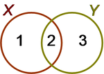
|Venn diagram for subsets of two sets.PNG|Venn diagram showing subsets of two sets ''X'' and ''Y''. | |||
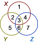
|Venn diagram for three sets.PNG|Venn diagram for three sets ''X'', ''Y'', and ''Z''. | |||
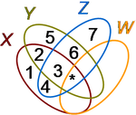
|Venn diagram for four sets.PNG|Venn diagram for four sets ''X'', ''Y'', ''Z'', and ''W''. | |||
|Venn diagram for five sets.PNG|Venn diagram for five sets ''X'', ''Y'', ''Z'', ''V'' and ''W''. | |||
|Logic gate with Venn diagram.PNG|A three-input logic gate (center) with its Venn diagram (top) and truth table (bottom). | |||
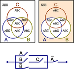
|Venn diagram for switch network A.PNG|Five-switch network with Venn diagrams for branches | |||
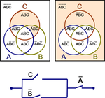
|Venn diagram for switch network B.PNG|Equivalent three-switch network with Venn diagrams for branches | |||
}} | }} | ||
| Line 139: | Line 200: | ||
|width=200 | |width=200 | ||
|lines=5 | |lines=5 | ||
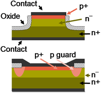
|Two diode structures.PNG|Mesa diode structure (top) and planar diode structure with guard-ring (bottom). | |||
|Planar bipolar transistor.PNG|A planar bipolar junction transistor as might be constructed in a [[integrated circuit]]. | |||
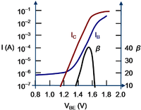
|Gummel plot.PNG|Gummel plot and current gain for a GaAs/AlGaAs heterostructure bipolar transistor. | |||
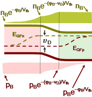
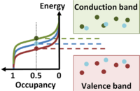
|Diode quasi-fermi levels.PNG|Quasi-Fermi levels and carrier densities in forward biased ''pn-''diode. | |||
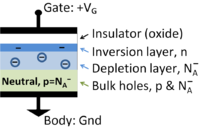
|MOS Capacitor.PNG|Cross section of MOS capacitor showing charge layers | |MOS Capacitor.PNG|Cross section of MOS capacitor showing charge layers | ||
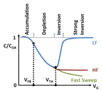
|MOS CV curves.PNG|Three types of MOS capacitance ''vs.'' voltage curves. ''V<sub>TH</sub>'' <nowiki>=</nowiki> threshold, ''V<sub>FB</sub>'' <nowiki>=</nowiki> flatbands | |MOS CV curves.PNG|Three types of MOS capacitance ''vs.'' voltage curves. ''V<sub>TH</sub>'' <nowiki>=</nowiki> threshold, ''V<sub>FB</sub>'' <nowiki>=</nowiki> flatbands | ||
| Line 144: | Line 209: | ||
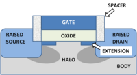
|MOSFET junction structure.PNG|A modern MOSFET | |MOSFET junction structure.PNG|A modern MOSFET | ||
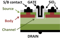
|UMOSFET.PNG|A power MOSFET; source and body share a contact. | |UMOSFET.PNG|A power MOSFET; source and body share a contact. | ||
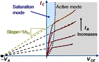
|Early effect.PNG|Two bipolar transistor modes, showing extrapolation of asymptotes to the Early voltage. | |||
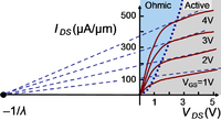
|Channel length modulation.PNG|Channel length modulation in 3/4μm technology. | |||
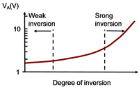
|Early voltage for 0.18mu process.PNG|Early voltage for MOSFETs from a 0.18μm process as a function of channel strength. | |||
|Silicon density of states.PNG|Calculated density of states for crystalline silicon. | |Silicon density of states.PNG|Calculated density of states for crystalline silicon. | ||
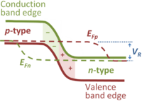
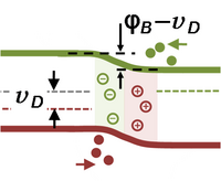
|Seimiconductor band bending.PNG|''Field effect'': At a gate voltage above threshold a surface inversion layer of electrons forms at a semiconductor surface. | |Seimiconductor band bending.PNG|''Field effect'': At a gate voltage above threshold a surface inversion layer of electrons forms at a semiconductor surface. | ||
| Line 154: | Line 222: | ||
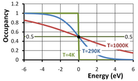
|Fermi function.PNG|Fermi occupancy function ''vs''. energy departure from Fermi level in volts for three temperatures | |Fermi function.PNG|Fermi occupancy function ''vs''. energy departure from Fermi level in volts for three temperatures | ||
|FCC Fermi surface.PNG|Fermi surface in '''k'''-space for a nearly filled band in the face-centered cubic lattice | |FCC Fermi surface.PNG|Fermi surface in '''k'''-space for a nearly filled band in the face-centered cubic lattice | ||
}} | |||
==More Devices== | |||
{{Gallery-mixed | |||
|caption=Devices | |||
|width=200 | |||
|lines=5 | |||
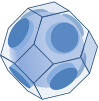
|Silicon conduction band ellipsoids.JPG|A constant energy surface in the silicon conduction band consists of six ellipsoids. | |Silicon conduction band ellipsoids.JPG|A constant energy surface in the silicon conduction band consists of six ellipsoids. | ||
|Planar Schottky diode.PNG|Planar Schottky diode with ''n<sup>+</sup>''-guard rings and tapered oxide. | |Planar Schottky diode.PNG|Planar Schottky diode with ''n<sup>+</sup>''-guard rings and tapered oxide. | ||
Latest revision as of 03:07, 22 November 2023
The account of this former contributor was not re-activated after the server upgrade of March 2022.
Angle brackets: & #x27E8; = ⟨ & #x27E9; = ⟩ & #10216; = ⟨ & #10217;= ⟩ <Φ|Ψ> <Φ|Ψ> <Φ|Ψ> ⟨Φ|Ψ⟩ ⟨Φ|Ψ⟩ ⟨Φ|Ψ⟩ ⟨Φ|Ψ⟩
Photos
| Photos | |||||||||||||||||||||||||||||
| |||||||||||||||||||||||||||||
Magnetism
| Magnetism | |||||||||||||||||||||||||||||
| |||||||||||||||||||||||||||||
Chemistry
| Chemistry | |||||||||||||||||||||||||||||
| |||||||||||||||||||||||||||||
Circuits
| Current sources | ||||||||||||||||||||||||||||||||||||||||||||||||||||||||||||||||||
| ||||||||||||||||||||||||||||||||||||||||||||||||||||||||||||||||||
| Small-signal circuits | |||||||||||||||||||||||||||||||||||||||||||||||||||||||||||||||||||||||||||
| |||||||||||||||||||||||||||||||||||||||||||||||||||||||||||||||||||||||||||
| Return ratio | |||||||||||||||||||||||||||||
| |||||||||||||||||||||||||||||
| Amplifiers | ||||||||||||||||||||||||||||||||||||||||||||||||||||||||||||
| ||||||||||||||||||||||||||||||||||||||||||||||||||||||||||||
Logic
| Logic and Venn diagrams | |||||||||||||||||||||||||||||
| |||||||||||||||||||||||||||||
Forces
| Forces | |||||||||||||||||||||||||||||||||||||||||||||||||||||||||||||||||||||||||||||||||||||||
| |||||||||||||||||||||||||||||||||||||||||||||||||||||||||||||||||||||||||||||||||||||||
Electromagnetism
| Electromagnetism | |||||||||||||||||||||||||||||
| |||||||||||||||||||||||||||||
Devices
| Devices | ||||||||||||||||||||||||||||||||||||||||||||||||||||||||||||||||||
| ||||||||||||||||||||||||||||||||||||||||||||||||||||||||||||||||||
More Devices
| Devices | |||||||||||||||||||||||||||||
| |||||||||||||||||||||||||||||
Vestibular system
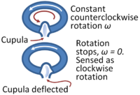
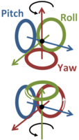
| Vestibular system | |||||||||||||||||||||||||||||
| |||||||||||||||||||||||||||||

