User:Milton Beychok/Gallery Subpages: Difference between revisions
imported>Milton Beychok No edit summary |
imported>Milton Beychok No edit summary |
||
| Line 1: | Line 1: | ||
=Evolution of steam generator designs== | |||
| | |||
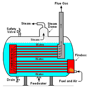
{{Image|Fire-tube Boiler.png|right|300px|Figure 2: Simplified schematic diagram of a fire tube boiler.}} | |||
;Fire-tube boilers<ref name=Nag>{{cite book|author=P.K. Nag|title=Power Plant Engineering|edition=3rd Edition|publisher=Tata McGraw-Hill|year=2008 |id=ISBN 0-07-064815-8}}</ref> | |||
In the late 18th century, various design configurations of fire-tube boilers began to be widely used for steam generation in industrial plants, railway [[locomotive]]s and [[steamboat]]s. Fire-tube boilers are so named because the fuel combustion product gases ([[flue gas]]) flow through tubes surrounded by water contained in an outer cylindrical drum (see Figure 2). Today, steam-driven locomotives and river boats have virtually disappeared and fire-tube boilers are not used for steam generation in modern utility power plants. | |||
However, they are still used in some industrial plants to generate [[Steam|saturated steam]] at [[pressure]]s of up to about 18 [[bar]] and at rates ranging up to about 25,000 kg/hour. In that range, fire-tube boilers offer low capital cost, operational reliability, rapid response to load changes and no need for highly skilled labor. | |||
The major shortcoming of fire-tube boilers is that the water and steam are contained within the outer cylindrical shell and that shell is subject to size and pressure limitations. The [[tensile stress]] (or [[hoop stress]]) on the cylindrical shell walls is a function of the shell [[diameter]] and the internal steam pressure:<ref>[http://courses.washington.edu/me354a/chap12.pdf Pressure vessels:Combined stress] From the website of the Mechanical Engineering Department at the [[University of Washington]]</ref> | |||
:<math>\sigma = \frac{p\, d}{2\, t}</math> | |||
{|border="0" cellpadding="2" | |||
|- | |- | ||
| | |align=right|where: <math>\sigma</math> | ||
|align=left|= tensile stress (or hoop stress), [[Pascal|Pa]] | |||
|- | |- | ||
| | |align=right|<math>p</math> | ||
|align=left|= Internal [[Pressure|gauge pressure]], Pa | |||
|- | |- | ||
| | |align=right| <math>d</math> | ||
|align=left|= internal diameter of cylindrical shell, m | |||
|- | |- | ||
| | |align=right|<math>t</math> | ||
|align=left|= thickness of cylindrical shell wall, m | |||
|} | |} | ||
The ever-growing need for increased quantities of steam at higher and higher pressures could not be provided by fire-tube boilers because, as can be seen in the above equation, both higher pressures and larger diameter shells led to prohibitively thicker and more expensive shells. | |||
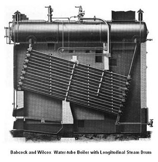
{{Image|B&W Longitudinal Drum, Water-Tube Boiler.JPG|right|325px|Figure 3: Representation of a water-tube boiler in the early 1900s.}} | |||
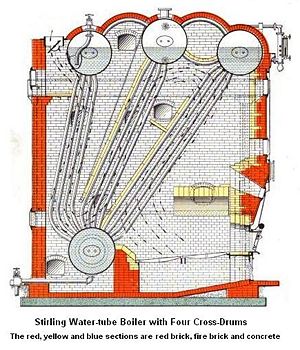
{{Image|Stirling Water-Tube Boiler.jpg|right|300px|Figure 4: A Stirling four drum boiler}} | |||
;Water-tube boilers | |||
Water-tube boilers with logitudinal steam drums, as in Figure 3,<ref>{{cite book|author=Babcock and Wilcox Company|title=Steam, Its Generation and Use|edition=35th Edition, 6th issue|publisher=Bartlett Orr Press, New York|year=1922}} [http://books.google.com/books?id=93DVAAAAMAAJ&pg=PA66&dq=Babcock+Steam&lr=&as_drrb_is=q&as_minm_is=0&as_miny_is=&as_maxm_is=0&as_maxy_is=&as_brr=0#v=snippet&q=longitudinal&f=false Google Books]</ref> were developed to allow increases in generated steam pressure and increased capacity. The water-tube boilers, in which water flowed through inclined tubes and the combustion product gases flowed outside the tubes, put the desired higher steam pressures in the small diameter tubes which could withstand the tensile stress of higher pressures without requiring excessively thick tubewalls.<ref name=Nag/> | |||
The relatively smaller steam drums (in comparison with the fire-tube shells) were also capable of withstanding the tensile stress of the desired higher pressures without needing excessively thick drum walls. | |||
The water-tube boiler went through several stages of design and development. The steam drum was arranged either parallel to the tubes (as shown in Figure 3) or transverse to the tubes, in which case the boiler was referred to as being a "cross drum" rather than a "longitudinal drum" boiler. Cross drum boilers could accomodate more tubes than longitudinal drum boilers and they were designed to generate steam pressures of up to about 100 bar and at rates ranging up to about 225,000 kg/hour. | |||
The next stage of development involved using slightly bent tubes, three to four steam drums and one to two mud drums at the bottom of the tubes (see Figure 4). The three sets of bent tubes, as shown in Figure 4, each represent a bank of tubes extending from the front of the steam drums back to the rear of the drums. Thus, the longer the steam drums, the more tubes were available and the more [[heat transfer]] surface was available. The tubes were bent slightly so that they entered and exited the steam drums radially. Baffles made of firebrick forced the flue gas to travel upwards from the mud drum to the right-hand steam drum and then downwards from the middle steam drum to the mud drum and finally upwards to the left-hand steam drum and out the flue gas exit in the upper left-hand corner. in essence, as shown in Figure 4, the baffles created a multi-pathway for the flue gas. | |||
The mud drums were suspended from the bottom of the tube banks and were free to move when the tube banks expanded as they heated up during boiler start-ups or contracted as they cooled down during boiler shutdowns. The purpose of the mud drum was to collect any solids that precipitated out from the water and the mud drums had provisions for blow-down of the collected solid. | |||
Referring again to Figure 4, the fuel combustion zone was located in the lower right-hand section of the boiler and the design included provisions for an adequate combustion air supply as well as adequate [[Flue gas stack|flue gas stack draft]]. | |||
Such designs were referred to as [[Stirling boilers]],<ref name=Stirling>{{cite book|author=The Engineering Staff of the Stirling Company Company |title=A Book on Steam for Engineers|edition=1st Edition|publisher=The Stirling Company|year=1905}} [http://books.google.com/books?id=VVNMAAAAMAAJ&pg=PA7&lpg=PA7&dq=%22Stirling+boiler%22&source=bl&ots=KEZG5FuItv&sig=q2LV61CEKeOUI3TCSMgBstbNN0s&hl=en&ei=KLUDS9GrOIGknQfsvtRl&sa=X&oi=book_result&ct=result&resnum=6&ved=0CB4Q6AEwBTgK#v=onepage&q=&f=false Google Books]</ref> named after Alan Stirling who designed his first boiler in 1883 and patented it in 1892, four years after forming the Stirling Boiler Company of [[New York]] in 1888.<ref name=ASME>[http://www.asme.org/Communities/History/Landmarks/Stirling_Watertube_Boilers.cfm Stirling Boilers] From the website of the [[American Society of Mechanical Engineers]] (ASME).</ref> One of the important advantages of the Stirling design was that the tubes were readily accessible, which made for easier inspection and maintenance or replacement of the tubes. | |||
The Stirling boilers with four steam drums were superseded by a simpler two drum design with a steam drum directly above a water (mud) drum and bent water tubes connecting the two drums. Later designs of the two drum version had a single flue gas path. In general, the Stirling boiler was capable of handling rapidly varying loads and was also adaptable to using vaious fuels.<ref name=Nag/> It could be said that the Stirling boilers were the forerunners of the modern steam generators used in power plants. | |||
The Babcock and Wilcox Company purchased and assimilated the Stirling Boiler Company in 1906 and began mass production of the Stirling boilers.<ref name=ASME/> Although widely used for large steam generating plants in the period between 1900 and [[World War II]] (the early 1940's), Stirling boilers are rarely seen today. | |||
Revision as of 23:11, 18 November 2009
Evolution of steam generator designs=
- Fire-tube boilers[1]
In the late 18th century, various design configurations of fire-tube boilers began to be widely used for steam generation in industrial plants, railway locomotives and steamboats. Fire-tube boilers are so named because the fuel combustion product gases (flue gas) flow through tubes surrounded by water contained in an outer cylindrical drum (see Figure 2). Today, steam-driven locomotives and river boats have virtually disappeared and fire-tube boilers are not used for steam generation in modern utility power plants.
However, they are still used in some industrial plants to generate saturated steam at pressures of up to about 18 bar and at rates ranging up to about 25,000 kg/hour. In that range, fire-tube boilers offer low capital cost, operational reliability, rapid response to load changes and no need for highly skilled labor.
The major shortcoming of fire-tube boilers is that the water and steam are contained within the outer cylindrical shell and that shell is subject to size and pressure limitations. The tensile stress (or hoop stress) on the cylindrical shell walls is a function of the shell diameter and the internal steam pressure:[2]
| where: | = tensile stress (or hoop stress), Pa |
| = Internal gauge pressure, Pa | |
| = internal diameter of cylindrical shell, m | |
| = thickness of cylindrical shell wall, m |
The ever-growing need for increased quantities of steam at higher and higher pressures could not be provided by fire-tube boilers because, as can be seen in the above equation, both higher pressures and larger diameter shells led to prohibitively thicker and more expensive shells.
- Water-tube boilers
Water-tube boilers with logitudinal steam drums, as in Figure 3,[3] were developed to allow increases in generated steam pressure and increased capacity. The water-tube boilers, in which water flowed through inclined tubes and the combustion product gases flowed outside the tubes, put the desired higher steam pressures in the small diameter tubes which could withstand the tensile stress of higher pressures without requiring excessively thick tubewalls.[1]
The relatively smaller steam drums (in comparison with the fire-tube shells) were also capable of withstanding the tensile stress of the desired higher pressures without needing excessively thick drum walls.
The water-tube boiler went through several stages of design and development. The steam drum was arranged either parallel to the tubes (as shown in Figure 3) or transverse to the tubes, in which case the boiler was referred to as being a "cross drum" rather than a "longitudinal drum" boiler. Cross drum boilers could accomodate more tubes than longitudinal drum boilers and they were designed to generate steam pressures of up to about 100 bar and at rates ranging up to about 225,000 kg/hour.
The next stage of development involved using slightly bent tubes, three to four steam drums and one to two mud drums at the bottom of the tubes (see Figure 4). The three sets of bent tubes, as shown in Figure 4, each represent a bank of tubes extending from the front of the steam drums back to the rear of the drums. Thus, the longer the steam drums, the more tubes were available and the more heat transfer surface was available. The tubes were bent slightly so that they entered and exited the steam drums radially. Baffles made of firebrick forced the flue gas to travel upwards from the mud drum to the right-hand steam drum and then downwards from the middle steam drum to the mud drum and finally upwards to the left-hand steam drum and out the flue gas exit in the upper left-hand corner. in essence, as shown in Figure 4, the baffles created a multi-pathway for the flue gas.
The mud drums were suspended from the bottom of the tube banks and were free to move when the tube banks expanded as they heated up during boiler start-ups or contracted as they cooled down during boiler shutdowns. The purpose of the mud drum was to collect any solids that precipitated out from the water and the mud drums had provisions for blow-down of the collected solid.
Referring again to Figure 4, the fuel combustion zone was located in the lower right-hand section of the boiler and the design included provisions for an adequate combustion air supply as well as adequate flue gas stack draft.
Such designs were referred to as Stirling boilers,[4] named after Alan Stirling who designed his first boiler in 1883 and patented it in 1892, four years after forming the Stirling Boiler Company of New York in 1888.[5] One of the important advantages of the Stirling design was that the tubes were readily accessible, which made for easier inspection and maintenance or replacement of the tubes.
The Stirling boilers with four steam drums were superseded by a simpler two drum design with a steam drum directly above a water (mud) drum and bent water tubes connecting the two drums. Later designs of the two drum version had a single flue gas path. In general, the Stirling boiler was capable of handling rapidly varying loads and was also adaptable to using vaious fuels.[1] It could be said that the Stirling boilers were the forerunners of the modern steam generators used in power plants.
The Babcock and Wilcox Company purchased and assimilated the Stirling Boiler Company in 1906 and began mass production of the Stirling boilers.[5] Although widely used for large steam generating plants in the period between 1900 and World War II (the early 1940's), Stirling boilers are rarely seen today.
- ↑ 1.0 1.1 1.2 P.K. Nag (2008). Power Plant Engineering, 3rd Edition. Tata McGraw-Hill. ISBN 0-07-064815-8.
- ↑ Pressure vessels:Combined stress From the website of the Mechanical Engineering Department at the University of Washington
- ↑ Babcock and Wilcox Company (1922). Steam, Its Generation and Use, 35th Edition, 6th issue. Bartlett Orr Press, New York. Google Books
- ↑ The Engineering Staff of the Stirling Company Company (1905). A Book on Steam for Engineers, 1st Edition. The Stirling Company. Google Books
- ↑ 5.0 5.1 Stirling Boilers From the website of the American Society of Mechanical Engineers (ASME).


